Site Manual
Alarm 2000 Iss 5
34
5.3 RESIDENTIAL FIRE INDICATOR PANEL
The RFIP is factory pre-wired and fully tested before delivery. After receipt of the panel,
the unit should be carefully unpacked and checked for any possible mechanical damage
during transportation. Report any damage to your supplier immediately.
5.3.1 Surface Mounting Instructions
1. Locate the position where the panel is to be sited.
2. Mark the position of the two mounting holes (240mm apart) and the cable cut-outs,
5 knockouts are available on the back and 5 on the top of the enclosure.
Note that Power and ELV cables are to be kept segregated.
3. Select the appropriate mounting hardware and prepare the two mounting holes.
4. Fix the top two points, leaving approximately 6 mm of the protrusion from the wall.
Mount the Panel and secure all mounting hardware.
5.3.2 Cable Terminations
AC Power
The 230 Vac input is terminated on the mains isolate switch and earth stud provided on
the rear inside of the enclosure.
The mains isolate switch delivers AC mains to the switch mode power supply and to RFIP
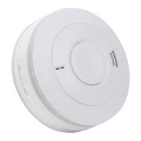
main and control Termination Board which supply mains power to the Smoke / Heat
Alarms.
Drawing no. F563 shows the block wiring diagram of the basic Alarm 2000 system.
Field Wiring
Terminate all field cabling provided on the Main Control Board and on the Termination
Boards of the optional modules as per drawing no. F563 and F564. The Block Wiring
Diagram uses 3 or 4 core cable to interface the Smoke / Heat Alarms depending on
whether the Isolator feature is used.
Cables should be terminated as required. Ensure all cables are neat and secured using
approved plastic ties.
Batteries
Fit Batteries into bottom of the enclosure.
RED Positive
BLACK Negative
BLUE Positive 1 / Negative 2
Using the mounting hardware provided, secure the front panel to the enclosure.
 Loading...