3-90
Confidential
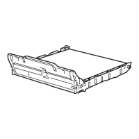
(5) Remove the Screw pan (S/P washer) M3.5x6 screw from the Drive ground plate.
(6) Release the Boss and remove the Drive ground plate from the Low-voltage power supply
PCB unit.
(7) Release the wiring of the LVPS-main harness ASSY.
Fig. 3-113
(8) Remove the two Taptite cup S M3x8 SR screws and two Taptite bind B M4x12 screws,
and remove the LVPS plate from the Main body.
Fig. 3-114
Screw pan (S/P washer) M3.5x6
Drive ground plate
LVPS-main harness ASSY
<Back side>
Boss
Low-voltage
power supply PCB unit
Taptite bind B M4x12
LVPS plate
Main body
Taptite bind B M4x12
Taptite cup S M3x8 SR
Taptite cup S M3x8 SR
<Back side>
 Loading...