12 of 24
Control Lever Removal
IMPORTANT: Refer to Trim/Tilt Switch Wire
Routing. Route trim/tilt wiring carefully when re-
mote control lever and trim/tilt switch wiring are
repositioned.
Refer to Remote Control Configuration
Diagrams before performing the following steps.
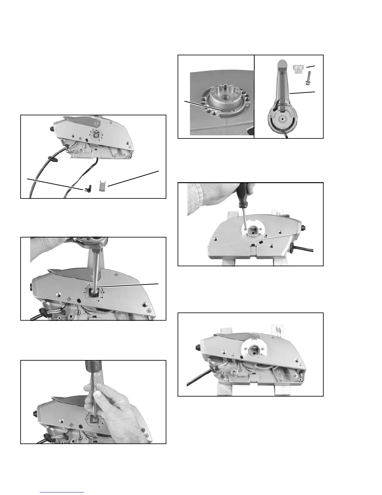
Remove back control cover. Compress tabs of
trim wire cover to remove cover. Remove cover
(standard configuration) and trim wire and
retainer from remote control.
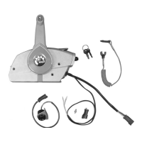
Loosen control lever retaining screw (12 mm)
three to four rotations counterclockwise.
Support the remote control housings. Strike the
screw head with a center punch and hammer to
unseat control lever.
Remove the screw and washer. Detach remote
control lever and joint from remote control. Place
flat tip screwdriver in notch of joint to pry from
control.
Loosen and remove two screws and neutral lock
plate from remote control housing.
Position neutral lock plate on appropriate side of
remote control housing. Install two screws with
lock washers through plate and torque screws to
35 in. lbs. (4 N·m).
1. Trim/tilt wire cover
2. Retainer
004868
1. Lever retaining screw
004875
004874
1
2
1
1. Lever
2. Joint
3. Notch
004878
004911
004876
004877
2
1
3