13 of 24
Trim/Tilt Switch Wire Routing
Refer to Remote Control Configuration
Diagrams. Note wire positions and routings.
Remove control lever cover and note wire posi-
tion and routing and position of wiring shield.
Route wire based on diagram for your specific
control lever configuration. The standard config-
uration is shown below (starboard side mount
with port side trim/tilt switch).
Route trim/tilt switch wires based on diagram for
your specific control lever configuration. Use the
trim/tilt wire retainer in all configurations. Route
wire through the correct cutout of control housing
cover. Refer to Remote Control Configuration
Diagrams.
IMPORTANT: Remote control cables must be
installed to check routing of tilt/trim wiring. Refer
to Install Remote Control Cables.
Torque screws to 36 in. lbs. (4 N·m). Install
remote control lever joint. Wire shield must be in
position as shown. Solid side of shield must be
down.
CAUTION
To prevent trim tilt switch wiring from
being damaged, route wires carefully and
provide adequate slack in wiring. Refer to
Remote Control Configuration Diagrams.
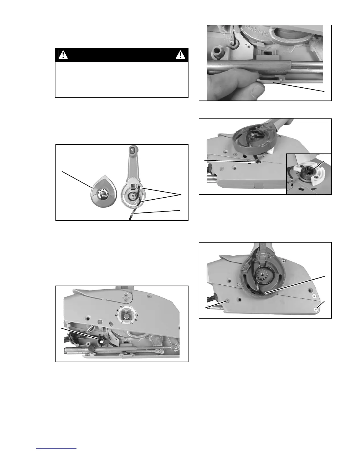
1. Cover
2. Wire routing
3. Shield
004879
Starboard Mount Wire Routing
1. Retainer, trim/tilt wire
004918
2
3
1
1
1. Cover, trim/tilt wire
004920
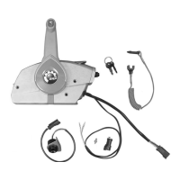
1. Wire cutout, control housing cover
2. Joint, control lever
004929
004919
1. Screws (2)
2. Shield
004928
1
1
2
2
1
1