8 of 24
Remote Control Configuration Diagrams
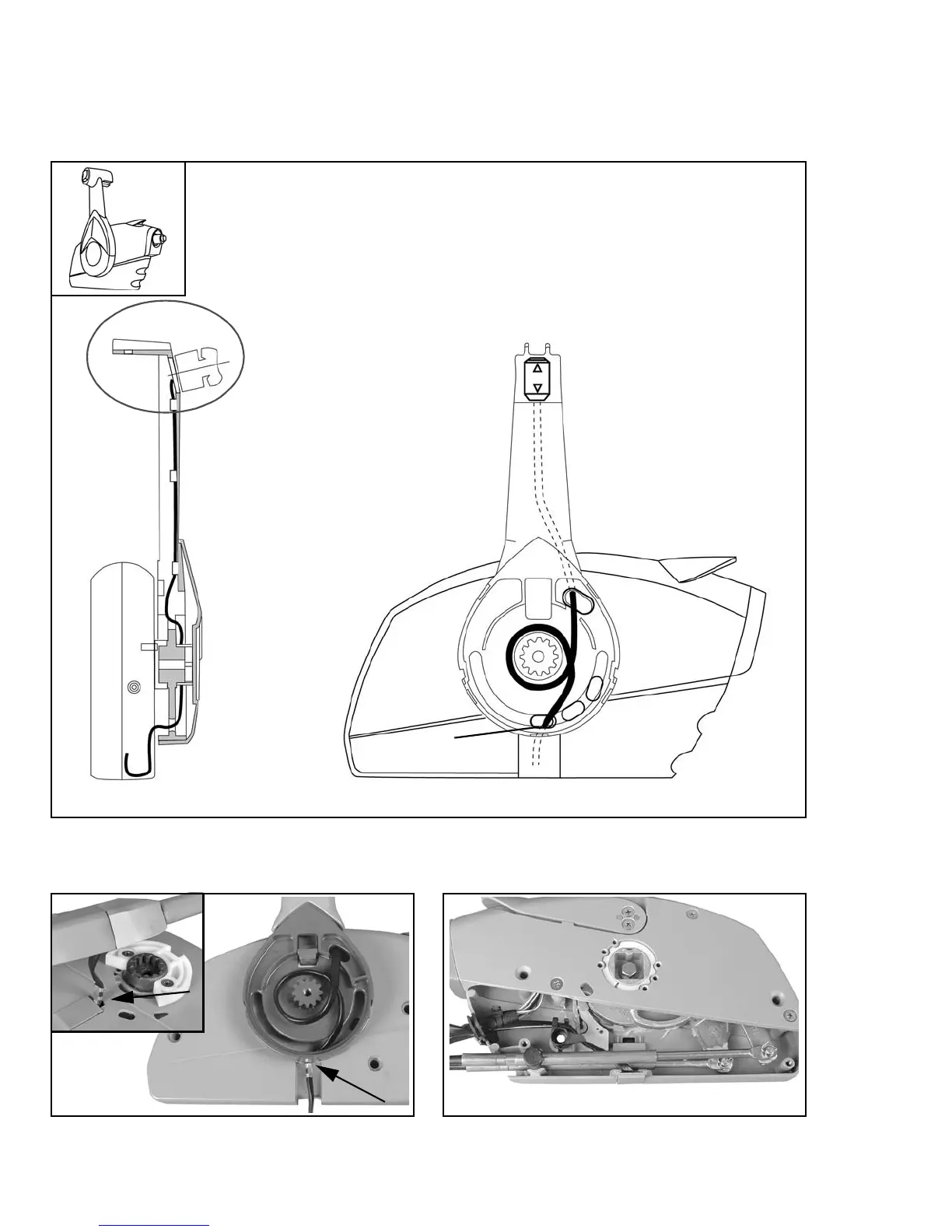
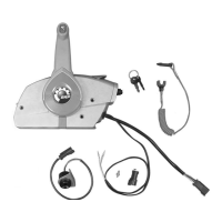
IMPORTANT: Refer to the following diagrams for proper trim/tilt switch wire routing. Route the trim/
tilt wiring through the correct hole in control housing to allow proper movement of lever and to prevent
trim/tilt switch wire damage.
Starboard Mount w/Port Side Trim/Tilt Switch
(Standard/Original Configuration)
2
1
3
1. Port side view of remote control
2. Forward view of remote control
3. Shield
004882
Shield
004916
004919
004918