15 of 24
IMPORTANT: Use Evinrude/Johnson Genuine
Parts or parts with equivalent characteristics, in-
cluding type, strength, and material.
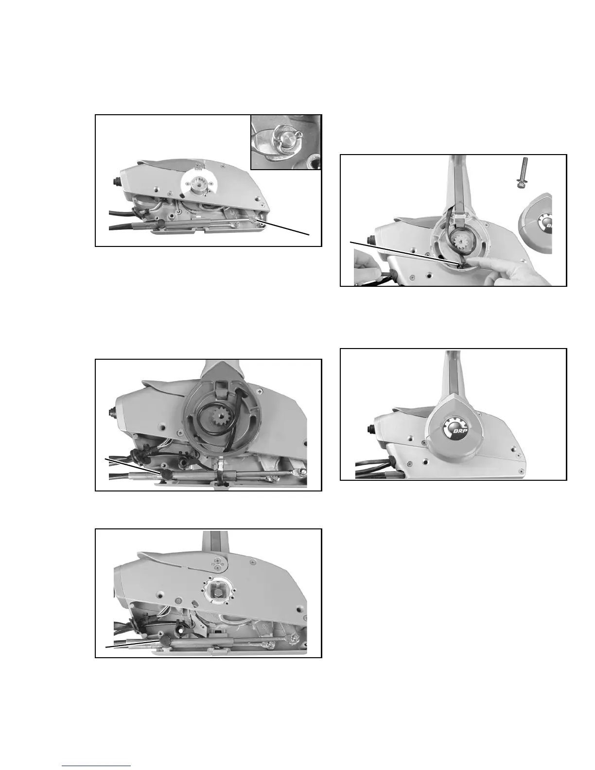
Install throttle cable and flat washer on to throttle
pin and secure with new cotter pin. Bend cotter
pin as shown.
IMPORTANT: Refer to Trim/Tilt Switch Wire
Routing before installing the remote control
housing’s rear cover.
Make sure shift and throttle cables are in the
trunnion pockets, and trim and tilt wire is properly
installed and does not rub or interfere with
movements of control box components.
Align throttle cable trunnion and wiring grommet
with back cover. Install back cover and screws.
Apply Triple-Guard grease to assembly screws.
Torque screws to 36 in. lbs. (4 N·m).
If removed, position remote control joint on drive
assembly and install remote control lever.
Align splines and position lever on joint. Neutral
lock lever must align with neutral lock plate.
Make sure trim/tilt wire shield is in position.
Secure lever with screw and washer. Torque
screw to 7 ft. lbs. (10 N·m). Align wire and install
cover.
Check operation and movement of control
levers. Make sure control locks in NEUTRAL
position and shift and throttle functions operate
smoothly. Refer to REMOTE CONTROL
OPERATION TEST.
1. Throttle cable
004885, 004890
Port Mounting Configuration
1. Trunnion pockets
004922
Starboard Mounting Configuration (Standard)
1. Trunnion pockets
004918
1
1
1
1. Shield
004887
004899
1