125
SYSTEM ANALYSIS
START CIRCUIT
5
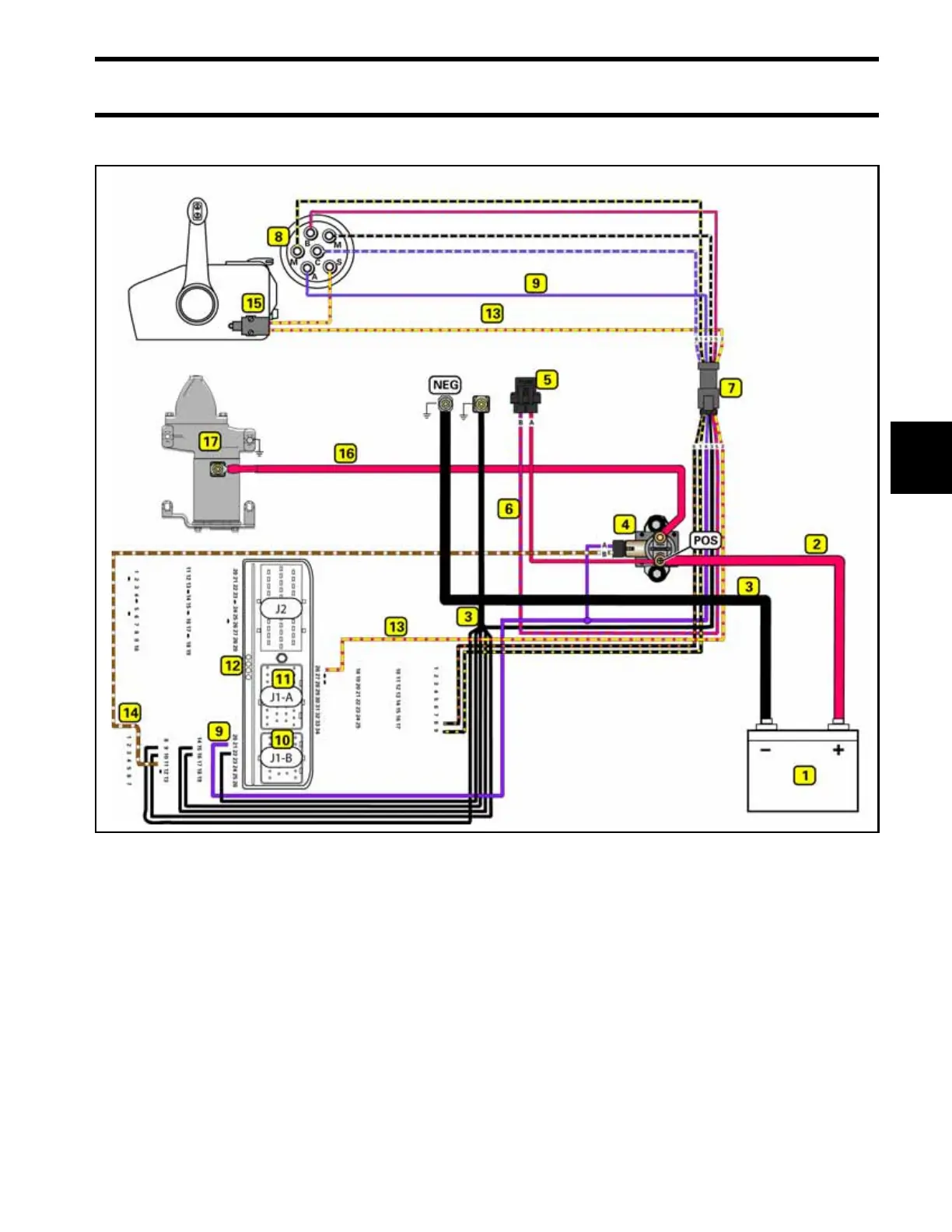
Start Circuit Diagram
1. Marine battery 10. 26-pin J1-B EMM connector
2. RED wire (POS) 11. 34-pin J1-A EMM connector
3. BLACK wire (NEG) 12. Engine Management Module (EMM)
4. Starter solenoid 13. YELLOW/RED wire, start
5. Fuse (10 amp) 14. BROWN/WHITE wire, start signal
6. RED/PURPLE wire 15. Neutral Safety Switch (remote control)
7. 6-pin connectors 16. RED starter motor cable
8. Ignition switch 17. Electric starter motor
9. PURPLE wire (switched B+)