38
INSTALLATION AND PREDELIVERY
BOAT RIGGING
• Use one battery switch for each outboard
installed.
• Use the appropriate sized wire and terminals for
all connections.
• Use AWG stranded copper wire.
Battery Switch Location
• Always locate battery switch(s) as close to the
battery(s) as possible.
• Locate switch so that it cannot be accidently
bumped or switched.
• Refer to the battery switch manufacturer’s
installation instructions for specific information
related to the installation of switch.
• Fasten all battery switches to solid surfaces.
• Route wiring as directly as possible.
• Support the battery switch as needed to prevent
abrasion.
• Use appropriate wiring and connectors.
• Seal all connections and terminals with liquid
neoprene or electrical sealer to prevent corro-
sion.
IMPORTANT: Insulate all battery positive (+)
terminals to prevent shorting.
Battery Switch Operation
• Select the primary battery for normal operation.
• Secondary batteries should only be selected for
emergency starting.
• ALL or BOTH switch position is for emergency
starting only.
Provide operator with the documentation sup-
plied by the battery switch manufacturer. Make
sure that the operator is informed of proper
battery switch operation.
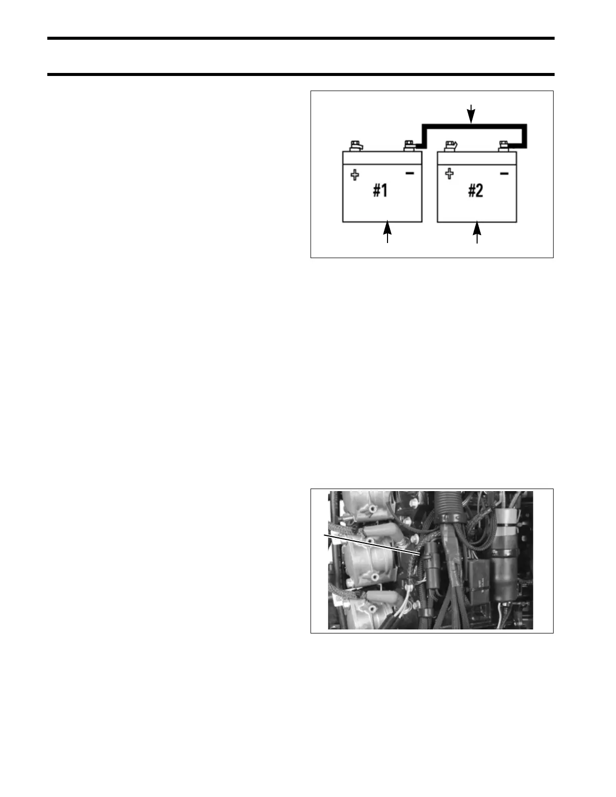
IMPORTANT: The negative (–) terminals of a
multiple 12-volt battery installation must be con-
nected together.
Auxiliary Battery Charge Isolator
Evinrude E-TEC 60° V outboards are equipped
with isolated battery charging capability. The iso-
lated charge connection must only be used to
charge a single 12-volt battery or two 12-volt bat-
teries wired in parallel.
IMPORTANT: Never connect an external battery
isolator to the stator of an Evinrude E-TEC out-
board.
Accessory Charge Lead Kit, P/N 5006253, is
routed from a connector on the outboard’s electri-
cal harness to the accessory battery.
IMPORTANT: The accessory charging kit must
never be connected to any battery of a 24-volt
electrical system.
1. Starting battery (primary)
2. Accessory battery (secondary)
3. Cable connecting negative (–) battery terminals
DRC7284
1. Accessory battery charge connector 004944
1 2
3
1