151
ELECTRICAL AND IGNITION
TILT/TRIM RELAY TEST
6
Use an inductive ammeter or connect a 0 to 100
amp ammeter in series with a heavy jumper
between the battery positive (+) terminal and the
starter positive (+) terminal.
Fluke model 334 or 336, Snap-On model MT110
or EETA501, and various other ammeters should
be available through local tool suppliers.
Attach or hold a vibration tachometer, such as a
Frahm
†
Reed tachometer, to the starter.
Complete the circuit with a heavy jumper between
the battery negative (–) terminal and the starter
frame.
Monitor the starter RPM and current draw.
• At 10,500 RPM the ammeter should show a
maximum of 30 A.
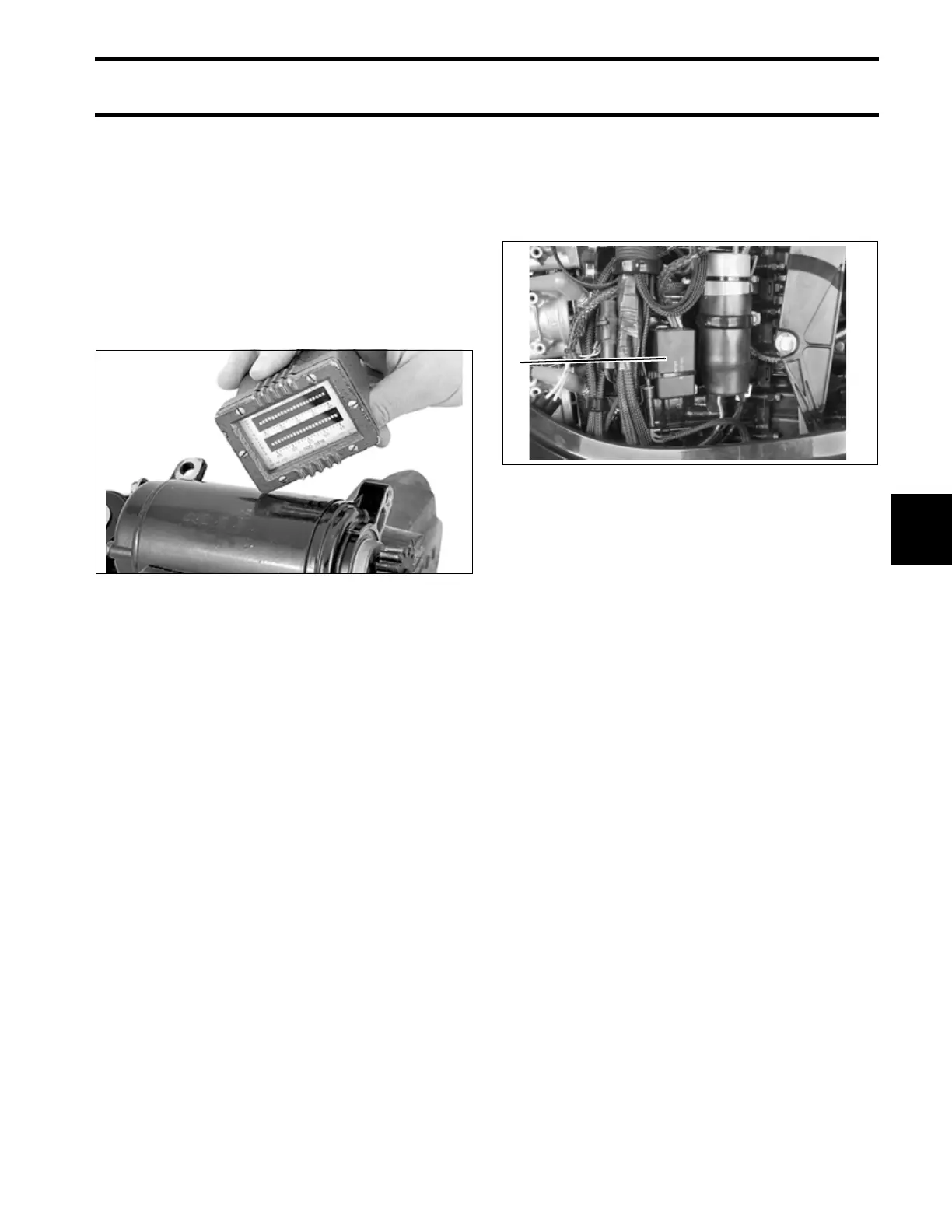
TILT/TRIM RELAY TEST
The tilt and trim (TNT) module contains the cir-
cuitry and relays required for power trim and tilt
operation.
The tilt and trim switch provides B+ input to
green/white or blue/white wire of the TNT module.
Operation
The relay activates when B+ input from the switch
is supplied to terminal 86 of the internal relays.
Terminal 87a connects to ground (B–).
Terminal 87 connects to B+.
Terminal 30 connects TNT motor.
Terminals 87a and 30 are connected when relay is
not activated. This supplies ground (B–) connec-
tion to TNT motor.
Terminals 87 and 30 are considered “normally
open.” B+ is applied to terminal 30 when relay is
activated. This supplies ground B+ connection to
TNT motor.
Refer to Tilt and Trim Module Diagram.
TYPICAL 24083
1. Tilt and trim module 005372
1