Effectivity: 916 i A / C24
Edition 0 / Rev. 1
BRP-Rotax Page 4-9
December 01 2023
Step Step Description Procedure
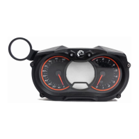
10 Check engine instru-
ments (Warning Indi-
cators and
Operational Limits)
and ensure compli-
ance with the operat-
ing limits.
HIC A: If a 12 V voltage drop be-
tween Terminal 2 and Terminal 8
at 916 i Type A, or at 916 i Type
C24 Terminal A and D (perma-
nent or oscillating) is detected
perform Lane and Ignition
Check. See abnormal operation
if the voltage drop still persists.
HIC B: If a 12 V voltage drop be-
tween Terminal 2 and Terminal
10 at 916 i Type A, or at 916 i
Type C24 Terminal A and D
(permanent or oscillating) is de-
tected perform a Lane and Igni-
tion Check. See abnormal
operation if the voltage drop still
persists.
Display CAN A/B: Check if oil
pressure has risen within 10
seconds after engine start and
monitor oil pressure.
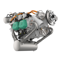
Example
(Symbolic)
Warning Lamp A: Check
Warning Lamp B: Check
Pilot Display: Check
11 Check state Caution
lamps 916 i Type
C24
”Procedure” AC-DC converter:
24 V drop to 0 Terminal X2.C.
Caution Lamp: 14 V Output
(EMS): OFF
Caution Lamp: 28 V Output
(AC): ON
Caution Lamp: Start/Backup
Power: OFF
Example
(Symbolic)
Start power Switch: OFF
Backup Battery Switch: OFF
Engine running: >1700 rpm
< 2400 rpm
12 Generator Switching Increase engine speed above
2400 rpm and hold for 8
seconds.
Example
(Symbolic)
Increase Throttle Position

 Loading...
