2.6.
Balance
of
Input
Amplifier
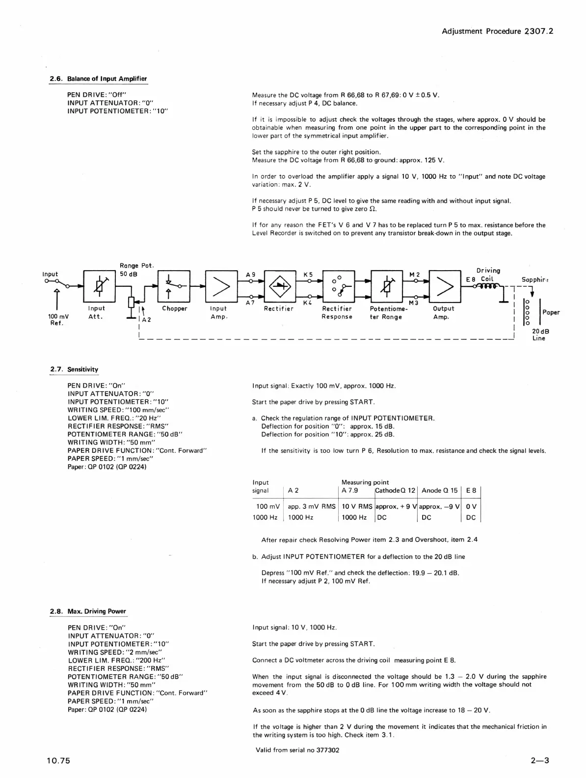
Input
T
PEN
DRIVE:
"Off"
INPUT
ATTENUATOR
:
"0"
INPUT
POTENTIOMETER:
"10"
Range
Pot.
f
SO
dB
~
t
Input
Chopper
100
mV
Att.
Ref.
2.
7.
Sensitivity
PEN
DRIVE:
"On"
INPUT
ATTENUATOR:
"a"
INPUT
POTENTIOMETER:
"10"
WRITING
SPEED:
"lOa
mm/sec"
LOWER
LIM.
FREO.:
"20
Hz"
RECTIFIER
RESPONSE:
"RMS"
POTENTIOMETER
RANGE:
"50
dB"
WRITING
WIDTH:
"50
mm"
PAPER DR
IVE
FUNCTION:
"Cont
.
Forward"
PAPER SPEED:
"1
mm/sec"
Paper:
OP
0102
(OP
0224)
2.S.
Max. Driving Power
PEN
DRIVE:
"On"
INPUT
ATTENUATOR:
"a"
INPUT
POTENTIOMETER:
"10"
WRITING
SPEED:
"2
mm/sec"
LOWER
LIM.
FREO.:
"200
Hz"
RECTIFIER
RESPONSE:
"RMS"
POTENTIOMETER
RANGE:
"50
dB"
WRITING
WIDTH:
"50
mm"
PAPER DR
IVE
FUNCTION
:
"Cont.
Forward"
PAPER SPEED :
"1
mm/sec"
Paper:
OP
0102
(OP
0224)
10.75
>
Input
Amp.
Adjustment Procedure
4307.2
Measure the
DC
voltage
from
R 66,68
to
R 67,69: a v
±0.5
V.
If
necessary adjust P 4,
DC
balance.
If
it
is
impossible
to
adjust check the voltages through
the
stages,
where approx. a v should
be
obtainable when measuring
from
one
point
in
the
upper
part
to
the corresponding
point
in
the
lower part
of
the symmetrical
input
amplifier.
Set the sapphire
to
the outer right position. .
Measure the
DC
voltage
from
R 66,68
to
ground: approx. 125 V.
I
n order to overload the
amplifier
apply a signal 10
V,
1000 Hz
to
"I
nput"
and note DC voltage
variation : max. 2
V.
If
necessary adjust P 5,
DC
level
to
give the
same
reading
with
and
without
input
signal.
P 5 should never
be
turned
to
give zero
n.
If
for
any reason the F ET's V 6 and V 7
has
to
be replaced
turn
P 5
to
max. resistance before
the
Level Recorder
is
switched on
to
prevent any transistor break·down in the
output
stage.
Rectifier Rectifier
Response
ter
Range
>
Output
Amp.
Driving
E8
Coil
Sapphir
'l
-l--l
i
II
I
Pop.,
I
2~dB
- - - - - - - - - - - - - - - - - - - - - - - -
--
Line
Input
signal : Exactly 100
mV
,
approx.1000
Hz
.
Start the paper drive by pressing
START
.
a.
Check the regulation range
of
INPUT
POTENTIOMETER.
Deflection
for
position
"0":
approx. 15 dB.
Deflection
for
position
"1
0"
: approx. 25 dB.
If
the sensitivity
is
too
low
turn
P 6, Resoluti
on
to
max. resistance and check the signal levels.
Input
signal
A2
Measuring
point
A 7.9 CathodeO 12 Anode
015
E 8
100
mV
app. 3
mV
RMS
10 V RMS approx. + 9 V approx.
-9
V a V
1000
Hz
1000 Hz 1000
Hz
DC DC DC
After
repair check Resolving
Power
item 2.3 and Overshoot, item
2.4
b.
Adjust
INPUT
POTENTIOMETER
for
a
deflection
to
the
20
dB line
Depress
"lOa
mV
Ref." and check the
deflection
: 19.9 - 20.1 dB.
If
necessary adjust P 2, 100
mV
Ref.
I
nput
signal : 10 V , 1000 Hz.
Start the paper drive
by
pressing
START.
Connect a
DC
voltmeter across the driving coil measuring
point
E 8.
When the
input
signal
is
disconnected the voltage should
be
1.3 - 2.0 V during the sapphire
movement
from
the
50
dB
to
a dB line. For
100
mm
writing
width
the
voltage
should
not
exceed 4 V.
As soon
as
the
sapphire stops
at
the
a dB line
the
voltage increase
to
18 -
20
V.
If
the voltage
is
higher than 2 V during the movement
it
indicates
that
the mechanical
friction
in
the
writing
system is
too
high. Check item 3 .1.
Valid
from
serial no 377302
2-3

 Loading...