1 .2 Paper Drive
System
I n
the
paper
drive system
the
Start,
Stop,
Forward and Reverse
funct
ions of
the
meter
is
controlled
by
electronically switch circuits.
The
motor
is
a
reversible
synchronous
motor
with
very
short
start
and
stop
t i mes
thu
s
avoiding
the
use
of
mechanical clutches.
When
the
Level Recorder
is
switched
to
one
of
the
"
Cont
. Record" or
"Automatic
Stop"
positions and a power failure should
occur
the
paper
dr
i
ve
system will
automatically
get "
stop"
informat
ion when Level Recorder s
tart
up again.
Stop
The
start/stop
flip-flop
is
locked
in
the
stop
position
by
+ 20 V supplied via
the
selector 0 6 and resistor R 230.
The
paper can stepwise be moved
forward
by
pressing
START
.
Continuous
Recording, forward:
The
start/stop
flip-flop
is
set
by
pressing
START
. This will change
the
output
from
the
inverter V
62-64
from
0
to
+ (check
point
" B" ) and
the
moto
r w
ill
start
in
forward
direction
.
+20
V applied
to
the
inverter V 59-
61
through
a section of PAPER DRIVE
FUNCTIONS will
change
the
voltage
in
check
poi
nt
" 1"
from
+
to
O.
Th
is 0
is
inverted
in
V 55 giving a blocking voltage
to
the
gate
for
automatic
stop
.
The
paper
drive
can
be
stopped
by
pushing
the
bu
t
ton
STOP.
Continuous
Recording, reverse:
As above
mentioned
except
that
a section
of
PAPER DRIVE FUNCTIONS
select
the
-
output
from
the
inverter V 82,83 (check
point
"C" ) causi
ng
the
motor
to
move in
the
opposite
direction.
Another
section of PAPER DRIVE
FUNCTIONS
activates
the
pen lift relay.
Automatic
Stop,
forward:
The
start
function
operates
as
for
Continuous
Recording
but
the
block
i
ng
voltage
to
the
gate
for
automatic
stop
is
removed
in
th
is posi
tion
of
PAPE R
DRIVE FUNCTIONS.
On
one
side
of
the
paper
wheel
is
a lamp which,
through
a slot
in
the
wheel,
will
give light
to
a
photodiode,
when
the
wheel
is
in
the
correct
stop
position.
The
signal
from
the
photodiode
activates a
Schmitt
-trigger
the
output
of
which, via
the
gate,
is
applied
to
the
start
/
stop
f
lip
-
flop
.
Automatic
Stop,
reverse:
As above
except
that
the
-
output
from
the
inverter V 82,83
is
used
to
operate
the
motor
.
The
pen lift relay
is
also activated.
2307
.1
Technical Description
Polar Recording:
This
position
is
used when
the
Level Recorder
is
used
with
the
Turntable
Type
3921
or
3922.
The
built-
in
stop
function
in
the
Turntable
will
stop
both
units
when
the
Turntable
has
completed
one
revolution.
Both units can be
started
from
either
the
Turntable
or
the
Level Recorder.
By
pushing STOP
on
the
Level Recorder
both
units
can
be
stopped.
To
continue
the
sweep
START
on
the
Level Recorder should be pushed.
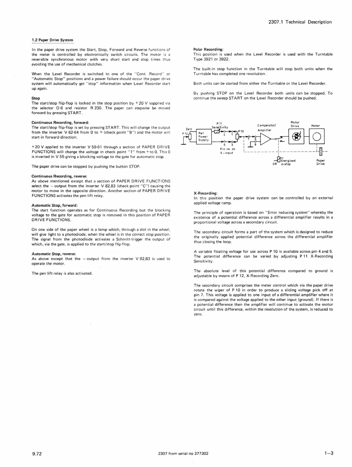
X-Recording:
Pin
no
.
on
X - i
nput
Co
mperator/
I~
1 8 I
Motor
Drive
Motor
1 . 1 1
1-
- - - - - - -
~
~
- - - - - - - - - -
Lm--
~nergized
Paper
08
in
stop
Dr
ive
In
this position
the
paper
drive system
can
be
controlled
by
an
external
applied voltage ramp.
The
principle
of
operation
is
based
on
"Error
reducing
system"
whereby
the
existence
of
a
potential
difference
across a differential amplifier results
in
a
proportional
voltage across a
secondary
circuit.
The
secondary circuit
forms
a
part
of
the
system
which
is
designed
to
reduce
the
originally applied
potential
difference
across
the
differential amplifier
thus
closing
the
loop.
A variable floating voltage
for
use across P 10
is
available across pin 4 and 5.
The
potential
difference can be varied
by
adjusting P
11
X-Recording
Sensitivity.
The
absolute level
of
this
potential
difference
compared
to
ground
is
adjustable
by
means
of
P 12, X-Recording Zero.
The
secondary
circuit comprises
the
meter
control
which
via
the
paper
drive
rotate
the
wiper
of
P 10
in
order
to
produce
a sliding voltage pick
off
at
pin 7. This voltage
is
applied
to
one
input
of
a differential amplifier
where
it
is
compared
against
the
voltage applied
to
the
other
input
(ground).
If
there
is
a
potentia
l difference
then
the
amplifier will
continue
to
activate
the
motor
circuit until this difference, within
the
resolution
of
the
system,
is
reduced
to
zero.
9.72
2307
from
seri
al
no
377302
1-3

 Loading...