5
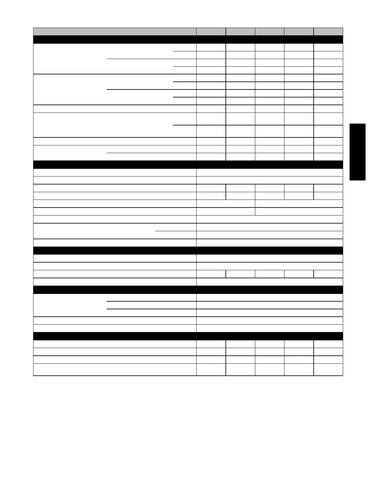
SPECIFICATIONS
UNIT SIZE 036070 048090 060110 066135 066155
RATINGS AND PERFORMANCE
Input Btuh*
Non-weatherized ICS
315JAV Upflow; all 315AAV
High 66,000 88,000 110,000 132,000 154,000
Low 43,500 58,000 72,500 87,000 101,500
315JAV Downflow/Horizontal
High 63,000 84,000 105,000 126,000 147,000
Low 43,500 58,000 72,500 87,000 101,500
Output Capacity (Btuh)†
Non-weatherized ICS
315JAV Upflow; all 315AAV
High 54,000 71,000 89,000 107,000 125,000
Low 35,000 47,000 59,000 70,000 82,000
315JAV Downflow/Horizontal
High 51,000 68,000 85,000 102,000 119,000
Low 35,000 47,000 59,000 70,000 82,000
AFUE† 80.0 80.0 80.0 80.0 80.0
Certified Temperature Rise Range - °F (°C)
High 30‐60
(17-33)
40‐70
(22-39)
40‐70
(22-39)
40‐70
(22-39)
45‐75
(25-42)
Low 30‐60
(17-33)
30‐60
(17-33)
25‐55
(14-30)
25‐55
(14-30)
30‐60
(17-33)
Certified External Static Pressure Heat/Cool 0.12/0.50 0.15/0.50 0.20/0.50 0.20/0.50 0.20/0.50
Airflow CFM‡
Heating High/Low 1060/615 1090/825 1330/1110 1725/1430 1775/1440
Cooling
1225 1400 2090 2100 2095
ELECTRICAL
Unit Volts-Hertz-Phase 115‐60‐1
Operating Voltage Range Min‐Max 104‐127
Maximum Unit Amps 9.0 9.6 15.1 14.9 15.0
Maximum Wire Length (Measure 1 Way in Ft (M) 30 (9.1) 29 (8.8) 29 (8.8) 30 (9.1) 29 (8.8)
Minimum Wire Size 14 12
Maximum Fuse or Ckt Bkr Size (Amps)** 15 20
Transformer (24v) 40va
External Control Heating 12va
Power Available Cooling 35va
Air Conditioning Blower Relay Standard
CONTROLS
Limit Control SPST
Heating Blower Control Solid‐State Time Operation
Burners (Monoport) 3 4 5 6 7
Gas Connection Size 1/2‐in. NPT
GAS CONTROLS
Gas Valve (Redundant)
Mfr. White‐Rodgers
Min. inlet pressure (In. W.C.) 4.5 (Natural Gas)
Max. inlet pressure (In. W.C.) 13.6 (Natural Gas)
Ignition Device Hot Surface
Factory‐installed orifice Size 43
BLOWER DATA
Direct‐Drive Motor HP (ECM) 1/2 1/2 1 1 1
Motor Full Load Amps 7.7 7.7 12.8 12.8 12.8
RPM (Nominal)‐Speeds 300‐1300 300‐1300 300‐1300 300‐1300 300‐1300
Blower Wheel Diameter x Width - In. (mm) 10 x 6
(254 x 152)
10 x 8
(254 x 203)
11 x 10
(279 x 254)
11 x 11
(279 x 279)
11 x 11
(279 x 279)
* Gas input ratings are certified for elevations to 2000 ft. (610 M) In USA for elevations above 2000 ft (610 M), reduce ratings 4 percent for each 1000 ft (305
M) above sea level. Refer to National Fuel Gas Code NFPA 54/ANSI Z223.1-2012 Table F.4 or furnace installation instructions.
† Capacity in accordance with U.S. Government DOE test procedures.
‡ Airflow shown is for bottom only return‐air supply for the as‐shipped speed tap. For air delivery above 1800 CFM, see Air Delivery table for other options. A
filter is required for each return‐air supply. An airflow reduction of up to 7 percent may occur when using the factory‐specified 4‐5/16 in. (110 mm) wide, high
efficiency media filter.
** Time-delay type is recommended.
ICS Isolated Combustion System
315AAV/JAV