WARNING: ELECTRICAL SHOCK HAZARD
Failure to follow this warning could result in serious
injury or death.
Blower access door switch opens 115-v power to control.
No component operation can occur. Do not bypass or
close switch with panel removed.
CAUTION: FURNACE MAY NOT OPERATE
Failure to follow this caution may result in furnace
operation stopping and water pipes freezing during cold
weather.
Furnace control must be grounded for proper operation or
control will lock out. Control is grounded through
green/yellow wire connected to gas valve and burner box
screw.
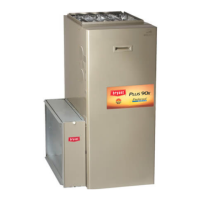
Fig. 30—Typical Gas Pipe Arrangement
A05057
COMBUSTION-AIR PIPE GROMMETS
GAS LINE GROMMET
GAS LINE
COMBUSTION
-AIR PIPE
VENT PIPE
VENT PIPE GROMMET
UNUSED 1/2 -IN.
DIAMETER GAS
CONN. HOLE
GAS LINE ENTRY
HOLE FILLER PLUG
NOTE: PIPE GROMMETS AND ENTRY HOLE FILLER
PLUGS ARE INCLUDED IN FACTORY-SUPPLIED
LOOSE PARTS BAG
A05057
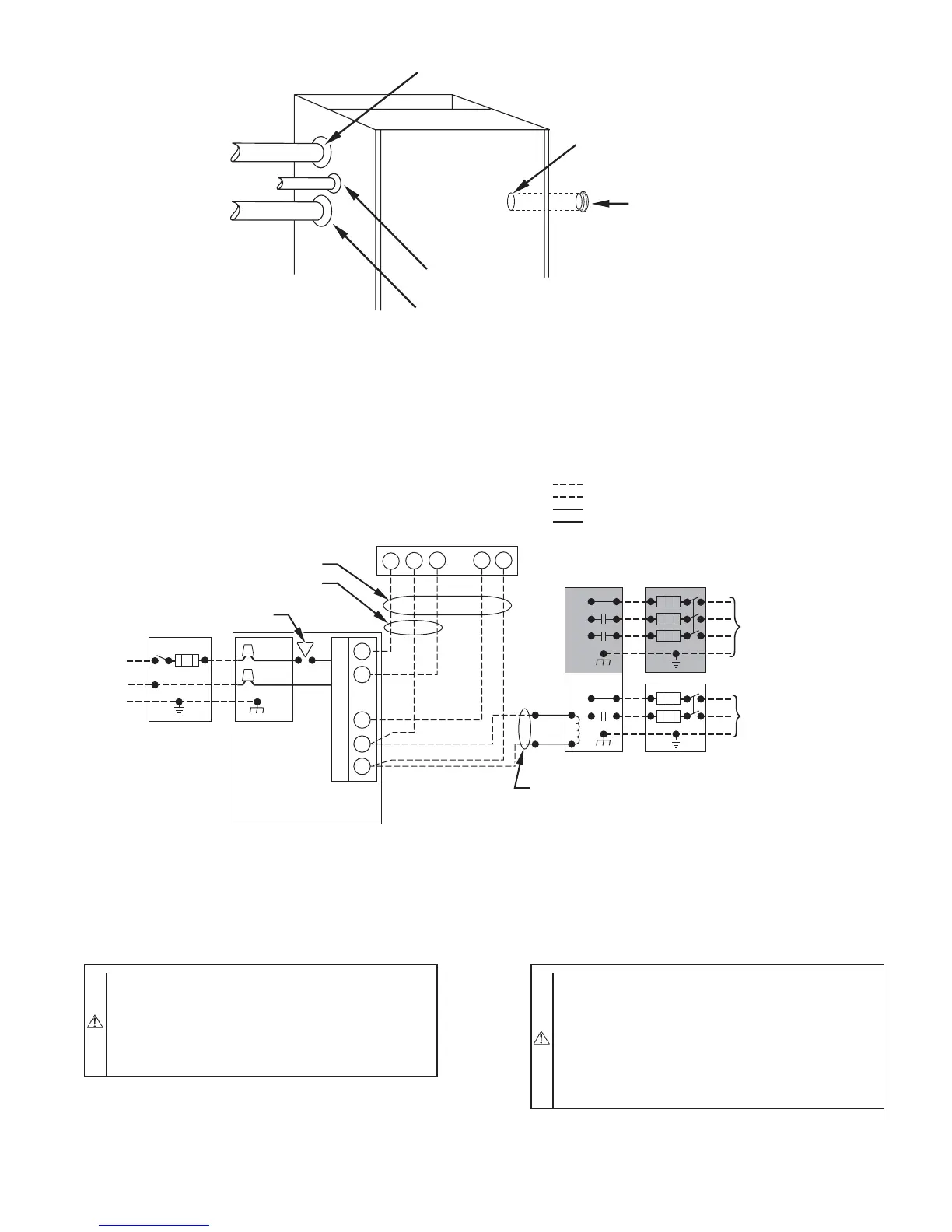
Fig. 31—Typical Heating and Cooling Application Wiring Diagram
A99440
115-V FIELD-
SUPPLIED
DISCONNECT
AUXILIARY
J-BOX
24-V
TERMINAL
BLOCK
THREE-WIRE
HEATING-ONLY
FIVE WIRE
NOTE 1
NOTE 2
FIELD-SUPPLIED
DISCONNECT
CONDENSING
UNIT
TWO
WIRE
FURNACE
C
O
N
T
R
O
L
R
G
COM
WCR GY
GND
GND
FIELD 24-V WIRING
FIELD 115-, 208/230-, 460-V WIRING
FACTORY 24-V WIRING
FACTORY 115-V WIRING
208/230- OR
460-V
THREE
PHASE
208/230-V
SINGLE
PHASE
BLOWER DOOR SWITCH
WHT
BLK
WHT
BLK
NOTES: Connect Y-terminal in furnace as shown for proper blower operation.
Some thermostats require a "C" terminal connection as shown.
If any of the original wire, as supplied, must be replaced, use
same type or equivalent wire.
W
Y/Y2
GND
THERMOSTAT
TERMINALS
1.
2.
3.
—25—
→