Outdoor draining of the furnace is permissible if allowed by local
codes. Caution should be taken when freezing ambient may freeze
drain pipe and prohibit draining.
WARNING: PERSONAL INJURY HAZARD
Caution should be taken to prevent draining where
slippery conditions could cause personal injuries.
Excessive condensate draining may cause saturated soil
conditions which could result in damage to plants.
C. Condensate Drain Protection
Freezing condensate left in condensate trap and drain line may
cause cracks, and possible water damage may occur. If freeze
protection is required, use condensate freeze protection accessory
or equivalent 3 to 6 watt per ft at 120–v and 40°F self-regulating,
shielded, and waterproof heat tape. See Installation Instructions
supplied with accessory or heat tape manufacturer’s recommenda-
tions.
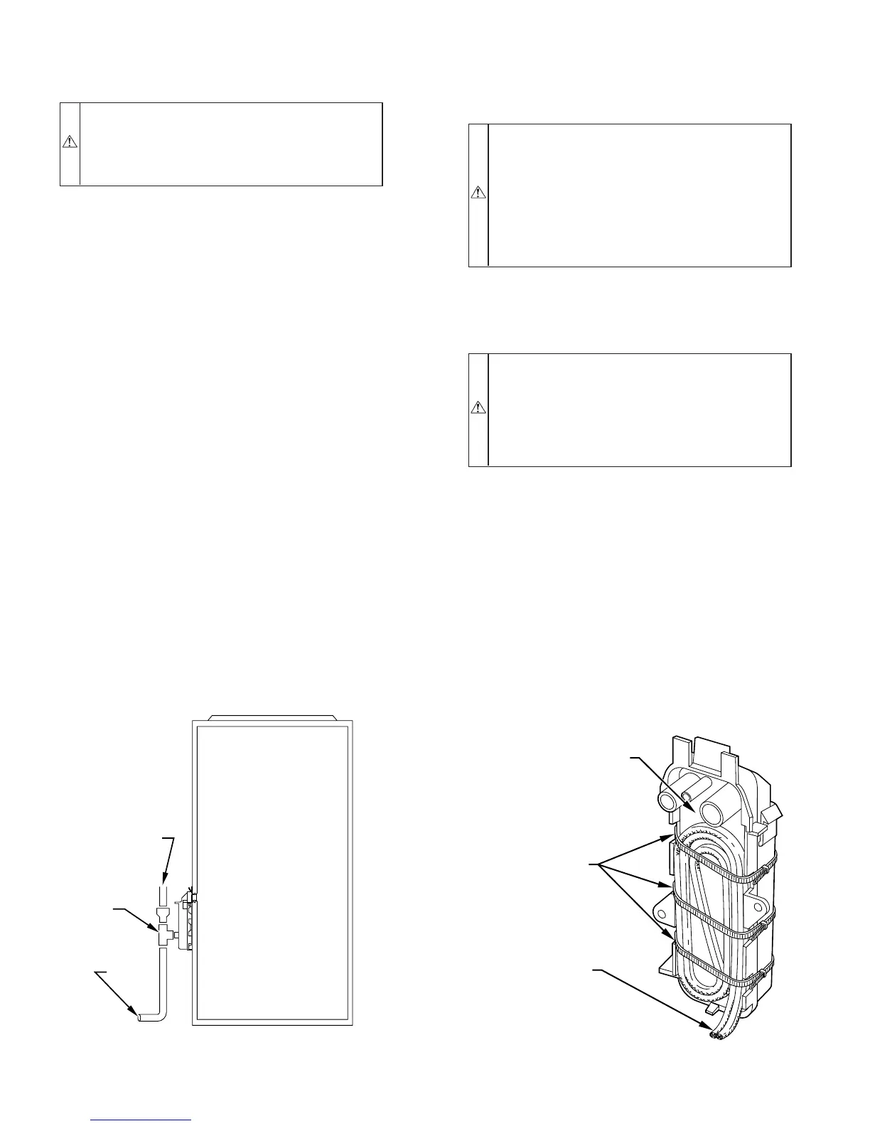
1. Fold heat tape in half and wrap on itself 3 times.
2. Locate heat tape between sides of condensate trap back.
(See Fig. 45.)
3. Use wire ties to secure heat tape in place. Wire ties can be
positioned in notches of condensate trap sides. (See Fig.
45.)
4. Wrap field drain pipe with remaining heat tape, approxi-
mately 1 wrap per ft.
5. When using field-supplied heat tape, follow heat tape
manufacturer’s instructions for all other installation guide-
lines.
START-UP, ADJUSTMENTS, AND SAFETY CHECK
I. GENERAL
1. Furnace must have a 115-v power supply properly con-
nected and grounded.
NOTE: Proper polarity and proper grounding must be maintained
for 115-v wiring. If polarity is incorrect, control LED status
indicator will flash rapidly and furnace will not operate.
2. Thermostat wire connections at terminals R, W, G, and
Y/Y2 must be made at 24-v terminal block on furnace
control.
3. Natural gas service pressure must not exceed 0.5 psig
(14-in. wc), and be no less than 0.16 psig (4.5-in. wc).
4. Blower access panel must be in place to complete 115-v
electrical circuit to furnace.
CAUTION: UNIT MAY NOT OPERATE
Failure to follow this caution may result in intermittent
unit operation.
These furnaces are equipped with a manual reset limit
switch in burner box. This switch will open and shut off
power to gas valve if an overheat condition (flame
rollout) occurs in burner enclosure. Correct inadequate
combustion-air supply or improper venting condition and
reset switch. DO NOT jumper this switch.
Before operating furnace, check flame roll-out manual reset switch
for continuity. If necessary, press button to reset switch.
II. PRIME CONDENSATE TRAP WITH WATER
CAUTION: UNIT MAY NOT OPERATE
Failure to follow this caution may result in intermittent
unit operation.
Condensate trap must be PRIMED or proper draining
may not occur. The condensate trap has 2 internal
chambers which can ONLY be primed by pouring water
into the inducer drain side of condensate trap.
1. Remove upper inducer housing drain connection cap. (See
Fig. 46.)
2. Connect field-supplied 1/2-in. ID tube to upper inducer
housing drain connection.
3. Insert field-supplied funnel into tube.
4. Pour 1 quart of water into funnel/tube. Water should run
through inducer housing, overfill condensate trap, and flow
into open field drain. (See Fig. 47.)
5. Remove funnel and tube from inducer housing and replace
drain connection cap and clamp.
III. PURGE GAS LINES
If not previously done, purge lines after all connections have been
made and check for leaks.
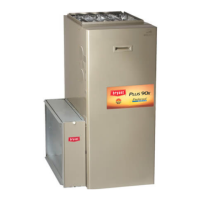
Fig. 44—Example of Field Drain Attachment
A94054
OPEN STAND
PIPE FOR
A/C OR
HUMIDIFIER
DRAIN
TEE
TO OPEN
DRAIN
Fig. 45—Condensate Trap Heat Tape
A93036
CONDENSATE TRAP
WIRE TIE(S)
HEAT TAPE
(3 WRAPS MINIMUM)
—42—