Do you have a question about the Bryant 353BAV and is the answer not in the manual?
Venting requirements for Canada, conforming to CSA B149 code and ULC S636 standards.
Commonwealth of Massachusetts requires compliance with 248 CMR, including CO detector and signage.
Caution regarding potential unit component damage due to improper application or installation.
Warning about hazards from improper installation, adjustment, alteration, or use.
Caution regarding sharp edges on sheet metal parts, advising care and protective gear.
Illustration of the furnace's multipoise orientations: Upflow, Downflow, Horizontal Left, Horizontal Right.
Conditions for using the furnace for construction heat, ensuring proper installation and operation.
Lists safety standards for installation, including NFGC, NFPA 90B, CSA B149.1, and NSCNGPIC.
Details requirements for combustion air, ventilation, and duct systems per industry standards.
Outlines requirements for gas piping, pressure testing, and electrical connections per NEC and CSA.
Provides a dimensional drawing of the furnace with connection points and overall dimensions.
Table listing unit size and corresponding dimensions A, D, and E in inches and millimeters.
Details minimum clearance requirements from combustible materials for furnace installation.
Illustrates required clearances to combustible materials for various furnace orientations.
Procedure to prevent damage to electronic components from electrostatic discharge during installation and servicing.
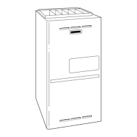
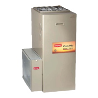
Introduces the 353BAV furnace, its type, multipoise capability, and vent applications.
Discusses the furnace's applications and general installation requirements.
Explains factory-shipped condensate trap location and tubing for upflow applications.
Diagram showing condensate trap configurations for different applications and drain connections.
Describes an alternate location for the condensate trap on the left-hand side casing for upflow applications.
Warning about carbon monoxide poisoning hazard if casing hole filler cap is not installed correctly.
Illustrates the factory-shipped tube configuration for upflow applications.
Instructions for inducer housing drain tube and condensate trap field drain attachment.
Details pressure switch tubing and unused upper drain connections.
Diagram showing tube configuration for downflow installation with a left-hand trap.
Instructions for relocating and connecting condensate trap tubing for downflow applications.
Warning about carbon monoxide poisoning hazard if casing hole filler cap is not installed correctly.
Diagram illustrating tube configuration for downflow installation with a right-hand trap.
Instructions for inducer housing drain tube and pressure switch tubing for downflow applications.
Refers to Condensate Drain section for attachment recommendations.
Diagram showing tube configuration for horizontal left discharge applications.
Procedures for relocating the condensate trap for horizontal left applications.
Warning about carbon monoxide poisoning hazard if casing hole filler cap is not installed correctly.
Illustrates attic location and working platform requirements for direct vent applications.
Procedures for relocating the condensate trap for attic applications.
Warning about carbon monoxide poisoning hazard if casing hole filler cap is not installed correctly.
Illustrates attic location and working platform requirements for non-direct vent applications.
Instructions for inducer housing drain tube and pressure switch tubing for non-direct vent applications.
Refers to Condensate Drain section for attachment recommendations.
Diagram showing tube configuration for horizontal right discharge applications.
Caution regarding unit operation hazards, specifically condensate trap and vent pipe installation.
Illustrates proper condensate drainage for upflow/downflow and horizontal furnace installations.
Caution regarding unit damage hazards when using the furnace for construction heat.
Illustration showing prohibited installation positions for the furnace.
Warning and requirements for installing the furnace in hazardous locations like garages.
Illustration showing installation requirements for furnaces in garages.
Specific cautions and requirements for non-direct vent (1-pipe) applications.
Explains provisions for adequate combustion, ventilation, and dilution air according to US and Canadian codes.
Table providing minimum free area requirements for combustion air openings based on BTUH input and duct configuration.
Table specifying minimum space volumes required for combustion air based on ACH and fan-assisted total input.
Details the standard method for determining space volume requirements for combustion air.
Illustrates methods for providing combustion air, ventilation, and dilution from outdoors.
Formula for calculating space volume for fan-assisted appliances like this furnace.
Illustrates methods for providing combustion air, ventilation, and dilution from indoors.
Instructions for installing leveling legs, if desired, for furnace installation.
Instructions for installing the furnace in upflow and downflow applications.
Instructions for installing the furnace in horizontal left or right discharge positions.
General requirements for designing and sizing the duct system.
Illustration of furnace installation on a combustible floor with a subbase.
Diagram showing how to modify duct flanges for proper installation.
Instructions for connecting the supply air duct to the furnace for various applications.
Guidelines for designing and installing the return air system to prevent negative pressure issues.
Warning about fire hazard from incorrect return air duct connections.
Illustration of crawlspace horizontal installation for both direct and non-direct vent systems.
Shows how to install grommets and filler plugs for combustion-air pipe connections.
Instructions for connecting the return-air duct to the furnace for upflow applications.
Details the filter arrangement options and installation for the furnace.
Warning about fire, carbon monoxide, and poisoning hazards from operating without a filter.
Diagram showing how to remove the bottom closure panel.
Instructions for removing and reinstalling the bottom closure panel.
Details gas piping installation requirements according to national and local codes.
Illustrates a typical gas pipe arrangement for furnace installation.
Table providing electrical specifications including voltage, wire size, and fuse/breaker ratings.
Shows typical gas pipe arrangement with grommets and filler plugs.
Instructions for making electrical connections, including wiring and grounding requirements.
Warning about electrical shock hazards during furnace installation.
Wiring diagram for heating and cooling with a 1-stage thermostat and condensing unit.
Wiring diagram for heating and cooling with a 2-stage thermostat and condensing unit.
Illustration of the disconnect switch and its connection to the furnace.
Warning about fire hazards related to using aluminum wire for electrical connections.
Instructions for making field 24-v connections at the furnace terminal block.
General guidelines for combustion air and vent pipe systems, including direct and non-direct vent applications.
Specific requirements for direct vent (2-pipe) systems, including termination kits.
Warning about carbon monoxide poisoning hazard during venting system operation.
Detailed wiring diagram for the furnace, showing electrical components and connections.
Key to symbols and abbreviations used in the wiring diagram.
Table listing approved materials for combustion-air and vent pipe systems according to ASTM specifications.
Warning about fire and explosion hazards associated with combustible solvent cements.
General guidelines for attaching the combustion air pipe to the furnace.
Diagram of the furnace control center, showing setup switches and terminal connections.
Instructions for assembling the combustion air pipe for non-direct vent systems.
Caution regarding intermittent furnace operation when using short pipe lengths.
Table detailing clearance requirements for direct vent termination locations.
Notes regarding vent termination placement and condensate management.
Table detailing clearance requirements for non-direct vent termination locations.
Notes regarding vent termination placement and condensate management.
Table showing maximum allowable vent pipe lengths based on altitude, unit size, and insulation.
Instructions for determining combustion air pipe connection and length, and vent pipe connection.
Diagram showing combustion-air and vent pipe connection configurations for different applications.
Warning about carbon monoxide poisoning and property damage hazards from inducer housing outlet cap.
Table showing maximum allowable pipe lengths for direct and non-direct vent systems based on altitude, unit size, and elbows.
Notes regarding disk usage, Canadian installations, and pipe size selection.
Continuation of the table for maximum allowable pipe lengths, including more altitude ranges.
Notes related to disk usage, Canadian installations, and pipe size selection.
Further continuation of the table for maximum allowable pipe lengths, covering additional altitude ranges.
Notes regarding pipe size, elbow usage, and termination length.
Caution regarding unit damage hazards if inducer housing outlet cap is not installed correctly.
Detailed guidelines for cutting, preparing, and cementing combustion air and vent pipes.
Diagram showing installation of pipe grommets and entry hole filler plugs.
Illustration showing pipe diameter transitions and elbow configurations.
Example calculation for determining pipe size based on altitude and elbow count.
Diagram showing the air intake housing plug fitting drain.
Diagram illustrating short vent system configurations.
General guidelines for vent termination, including clearance and placement considerations.
Guidelines for extending exposed sidewall pipes, including insulation and diameter determination.
Diagram showing combustion air and vent pipe termination for direct vent systems.
Diagram showing vent pipe termination for non-direct vent systems.
Table listing available vent termination kits for direct vent systems.
Instructions for installing concentric vent/combustion air termination kits.
Instructions for condensate drain installation, including trap relocation and priming.
Diagram illustrating an example of field drain attachment.
Recommendations for protecting condensate traps and drain lines from freezing.
Procedures for start-up, adjustment, and safety checks of the furnace.
Diagram showing the inducer housing drain cap.
Illustration showing how to fill the condensate trap with water.
Instructions for priming the condensate trap with water.
Instructions for purging gas lines and checking for leaks.
Detailed explanation of the furnace's sequence of operation in various modes.
Explanation of two-stage heating operation with a single-stage thermostat using adaptive mode.
Describes the inducer prepurge period for both low-heat and high-heat operations.
Explains continuous blower operation and speed selection.
Instructions for operating the furnace with a heat pump, including timing sequences.
Explains operation with a Thermidistat, including dehumidification and cooling exceptions.
Wiring diagram for two-stage furnace with a single-speed air conditioner.
Wiring diagram for two-stage furnace with a two-speed air conditioner.
Wiring diagram for two-stage furnace with a single-speed heat pump (dual fuel).
Wiring diagram for two-stage furnace with a two-speed heat pump (dual fuel).
Wiring diagram for dual fuel thermostat with furnace and heat pump.
Wiring diagram for dual fuel thermostat with furnace and single-speed heat pump.
Wiring diagram for single-stage thermostat with furnace and two-speed air conditioner.
Notes and important setup instructions for various thermostat and heat pump configurations.
Explains continuous blower operation and speed selection.
Instructions for operating the furnace with a heat pump, including timing sequences.
Procedure for performing a component self-test to diagnose system issues.
Section detailing various adjustments for furnace operation.
Instructions for setting the gas input rate, including altitude derating and orifice selection.
Caution regarding reduced furnace life from improper gas valve regulator adjustment.
Table providing orifice sizes and manifold pressures for correct inputs based on altitude and gas gravity.
Continuation of the table for orifice size and manifold pressures, covering more altitudes.
Diagram of the redundant automatic gas control valve.
Procedure for verifying natural gas input rate by clocking the gas meter.
Emphasizes the importance of checking and verifying burner orifice size.
Table showing altitude derate multipliers for the USA.
Table providing gas rates in cubic feet per hour based on test dial seconds and revolution.
Instructions for setting the temperature rise and checking for excessive restrictions.
Table for selecting blower speed based on unit size and external static pressure.
Instructions for adjusting the blower off delay for improved comfort.
Section detailing checks for safety controls like primary limit and pressure switch.
Checklist for direct vent (2-pipe) installation steps.
Checklist for start-up procedures, including gas input rate and temperature rise.
Checklist items for verifying safety control operation.
Checklist for non-direct vent (1-pipe) installation steps.
Checklist for start-up procedures, including gas input rate and temperature rise.
Checklist items for verifying safety control operation.
| Model | 353BAV |
|---|---|
| Type | Gas Furnace |
| Efficiency Rating | High Efficiency |
| Blower Type | Variable Speed |
| Stages | Two-Stage |
| Blower Motor | Variable Speed ECM |
| Vent Type | Direct Vent |
| Fuel Type | Natural Gas |
| Warranty | 10-year parts limited warranty upon registration |


 Loading...