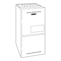
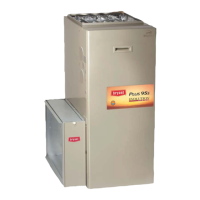
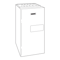
EasyManua.ls Logo

Bryant 352MAV - User Manual

Bryant 352MAV
52 pages
Print Icon
To Next Page IconTo Next Page
Loading...
NOTE: Read the entire instruction manual before starting the
installation.
This symbol indicates a change since the last issue.
TABLE OF CONTENTS
Safety Considerations.....................................................................2
Introduction ....................................................................................2
Codes and Standards......................................................................5
Safety.........................................................................................5
General Installation...................................................................5
Combustion and Ventilation Air ..............................................5
Duct Systems ............................................................................5
Acoustical Lining and Fibrous Glass Duct..............................5
Gas Piping and Gas Pipe Pressure Testing..............................5
Electrical Connections ..............................................................5
Electrostatic Discharge (ESD) Precautions Procedure..................5
Applications....................................................................................6
General ......................................................................................6
Upflow Applications.................................................................6
Downflow Applications............................................................9
Horizontal Left (Supply-Air Discharge)
Applications ............................................................................10
Horizontal Right (Supply-Air Discharge) Applications ........12
Location........................................................................................13
General ....................................................................................13
Furnace Location Relative to Cooling
Equipment ...............................................................................14
Hazardous Locations...............................................................15
Installation ....................................................................................15
Leveling Legs (If Desired).....................................................15
Installation in Upflow and Downflow
Applications ............................................................................15
Installation in Horizontal Applications ..................................15
Air Ducts.................................................................................16
General Requirements .......................................................16
Ductwork Acoustical Treatment .......................................17
Supply Air Connections ....................................................17
Return Air Connections.....................................................17
Filter Arrangement..................................................................18
Bottom Closure Panel.............................................................19
Gas Piping...............................................................................19
Electrical Connections ............................................................20
115-V Wiring.....................................................................20
24-V Wiring.......................................................................21
Accessories ........................................................................22
Direct Venting.........................................................................22
Removal of Existing Furnaces from Common Vent
Systems ..............................................................................22
Combustion-Air and Vent Piping .....................................25
Concentric Vent and Combustion-Air Termination
Kit Installation...................................................................30
Multiventing and Vent Terminations................................34
Condensate Drain....................................................................34
General...............................................................................34
Application.........................................................................34
Condensation Drain Protection .........................................34
Start-Up Adjustment and Safety Check ......................................34
General ....................................................................................34
Prime Condensate Trap With Water......................................36
Purge Gas Lines......................................................................36
Sequence of Operation............................................................37
Two-Stage Heating With Single-Stage Thermostat
(Adaptive Mode)................................................................37
Two-Stage Heating With Two-Stage Thermostat
(Non-Adaptive Heating Mode) .........................................43
Cooling Mode....................................................................44
Thermidistat Mode ............................................................44
Continuous Blower Mode .................................................45
Heat Pump .........................................................................45
Component Self-Test.........................................................45
Operate Furnace.................................................................46
Furnace Restart..................................................................46
Adjustments .............................................................................46
Set Gas Input Rate ............................................................46
Set Temperature Rise ........................................................48
Adjust Blower Off Delay (Heat Mode)............................48
Set Thermostat Heat Anticipator ......................................49
Check Safety Controls............................................................49
Checklist..................................................................................49
A93040
installation, start-up,
and operating instructions
2-STAGE, DIRECT VENT
CONDENSING GAS FURNACE
Cancels: II 352M-60-6 II 352M-60-7
3-05
352MAV
Series C
—1—

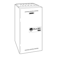
Table of Contents

Other manuals for Bryant 352MAV

Questions and Answers

  • C
    Cristina IbarraAug 14, 2025
    Why is my Bryant Furnace ignition proving failing?
    • R
      rodneyryanAug 14, 2025
      If your Bryant Furnace is experiencing ignition proving failure, several factors could be at play. Make sure that the gas valve is not defective or turned off. Check for oxide buildup on the flame sensor and clean it with fine steel wool if necessary. Ensure the flame sense current is within the proper range (0.5 microamps D.C. min., 4.0 - 6.0 nom. in HIGH HEAT). Verify the green wire is securely connected to the furnace sheet metal and that the flame sensor is ungrounded. Also, check the manual valve shut-off, inspect for a defective hot surface igniter, confirm control ground continuity, and address any inadequate flame carryover or rough ignition issues. Finally, ensure that the inlet gas pressure is adequate.
  • R
    robinadamsAug 17, 2025
    What to do if the limit or flame roll-out switch is open in my Bryant 352MAV Furnace?
    • D
      Donald JohnsonAug 17, 2025
      If the limit or flame roll-out switch is open, check the following: a dirty filter or restricted duct system, a loose blower wheel, a defective blower motor or capacitor, defective switch or connections, and inadequate combustion air supply. If the flame roll-out switch or fuse link is open, you may need to manually reset it or replace it.
  • C
    Carrie FinleyAug 20, 2025
    What causes a Bryant 352MAV to experience a gas heating lockout?
    • P
      Paula BerryAug 20, 2025
      If your Bryant Furnace is experiencing a gas heating lockout, you should check for a mis-wired gas valve and a defective control (valve relay).
  • T
    Thomas SampsonAug 25, 2025
    What does it mean if the secondary voltage fuse is open in my Bryant 352MAV, and how do I fix it?
    • S
      Sydney GarrettAug 25, 2025
      If the secondary voltage fuse is open, check for a short-circuit in the secondary voltage (24VAC) wiring.
  • E
    Elizabeth WebbAug 27, 2025
    What should I do if the pressure switch did not open in my Bryant Furnace?
    • C
      Caleb Wilson Jr.Aug 27, 2025
      If the pressure switch did not open, check for obstructed pressure tubing or a pressure switch stuck closed. Also, check for a short-circuit in secondary voltage (24VAC) wiring.
  • A
    Ashley RiveraAug 30, 2025
    What to do if low-heat pressure, draft safeguard, or aux-limit switch did not close or reopened in my Bryant Furnace (downflow only)?
    • M
      Michelle CalhounAug 30, 2025
      Check for a defective blower motor or capacitor, a restricted vent, proper vent sizing, low inducer voltage (115VAC), disconnected or obstructed pressure tubing, excessive wind, a defective inducer motor, a defective pressure switch, or an inadequate combustion air supply.
  • V
    vanessa11Sep 2, 2025
    What does it mean when my Bryant 352MAV has an abnormal flame-proving signal?
    • L
      lucastimothySep 2, 2025
      Check for a leaky or stuck-open gas valve.
  • K
    Kaitlyn HessSep 6, 2025
    What to do if low-heat pressure, draft safeguard, or aux-limit switch is open while high-heat pressure switch is closed in Bryant 352MAV?
    • M
      Maria HobbsSep 6, 2025
      Check if the pressure switch is stuck open or if the pressure tubing is disconnected or obstructed.
  • K
    Katie HerreraSep 9, 2025
    Why is the blower on after power up in my Bryant Furnace?
    • C
      Cheryl CainSep 9, 2025
      The blower runs for 90 seconds if the unit is powered up during a call for heat (R-W closed).

Summary

Safety Considerations

Introduction

Installation

Minimum Inches Clearance to Combustible Construction

Specifies minimum clearance requirements to combustible materials.

Codes and Standards

I. Safety

Lists safety standards and codes for installation.

II. General Installation

Covers general installation requirements and references.

Electrostatic Discharge (ESD) Precautions Procedure

Applications

I. General

General notes on assembly and modifications for applications.

II. Upflow Applications

Details for installing the furnace in an upflow orientation.

III. Downflow Applications

Details for installing the furnace in a downflow orientation.

IV. Horizontal Left (Supply-Air Discharge) Applications

Details for installing the furnace in a horizontal left orientation.

V. Horizontal Right (Supply-Air Discharge) Applications

Details for installing the furnace in a horizontal right orientation.

Location

I. General

General requirements for furnace location and protection.

II. Furnace Location Relative to Cooling Equipment

Guidelines for locating furnace relative to cooling equipment.

III. Hazardous Locations

Specific installation requirements for hazardous locations like garages.

Installation

I. Leveling Legs (If Desired)

Instructions for installing leveling legs if needed.

II. Installation in Upflow and Downflow Applications

Instructions for upflow and downflow installation configurations.

III. Installation in Horizontal Applications

Instructions for installing the furnace in horizontal applications.

Air Ducts

A. General Requirements

General requirements for air duct system design and sizing.

B. Ductwork Acoustical Treatment

Guidelines for internal acoustical lining or fibrous ductwork.

C. Supply Air Connections

Instructions for connecting supply air ducts.

D. Return Air Connections

Requirements for connecting return air systems to the furnace.

Filter Arrangement

Bottom Closure Panel

Gas Piping

Electrical Connections

J-Box Relocation

Instructions for relocating the auxiliary junction box.

Direct Venting

A. Removal of Existing Furnaces from Common Vent Systems

Steps for removing old furnaces from common vent systems.

B. Combustion-Air and Vent Piping

Guidelines for combustion-air and vent piping materials and installation.

C. Combustion-Air and Vent Pipe Diameter

Determining the correct diameter for combustion-air and vent pipes.

Extended Exposed Sidewall Pipes

Instructions for extending sidewall pipes and insulation requirements.

Two-Pipe Termination Kit

Instructions for installing a two-pipe termination kit.

D. Concentric Vent and Combustion-Air Termination Kit Installation

Steps for installing a concentric vent and combustion-air termination kit.

Concentric Vent;Air Termination Kit

Steps for installing a concentric vent/air termination kit.

E. Multiventing and Vent Terminations

Guidelines for venting multiple furnaces and termination placement.

Condensate Drain

A. General

General information on condensate trap installation and use.

B. Application

How to combine furnace, AC, and humidifier drains.

C. Condensate Drain Protection

Measures to protect condensate drain lines from freezing.

II. Prime Condensate Trap with Water

Procedure for priming the condensate trap with water.

III. Purge Gas Lines

Steps to purge gas lines and check for leaks.

Sequence of Operation

A. Two-Stage Heating With Single-Stage Thermostat (Adaptive Mode)

How the furnace operates in two-stage heating with a single-stage thermostat.

B. Two-Stage Heating With Two-Stage Thermostat (Non-Adaptive Heating Mode)

How the furnace operates in two-stage heating with a two-stage thermostat.

C. Cooling Mode

Details operation of the furnace in various cooling modes.

D. Thermidistat Mode

Operation when using a Thermidistat for dehumidification control.

E. Continuous Blower Mode

How to operate the blower continuously.

F. Heat Pump

Operation when installed with a heat pump.

G. Component Self-Test

Procedure for testing furnace components.

H. Operate Furnace

Following operating instructions.

I. Furnace Restart

Procedure for restarting the furnace.

Adjustments

A. Set Gas Input Rate

Procedure for setting the correct gas input rate based on altitude.

B. Set Temperature Rise

Procedure for setting the correct temperature rise.

C. Adjust Blower Off Delay (Heat Mode)

Adjusting the blower off delay for heating mode comfort.

D. Set Thermostat Heat Anticipator

Setting the thermostat's heat anticipator for proper cycle control.

Check Safety Controls

1. Check Primary Limit Control

Procedure for testing the primary limit control for overheating.

2. Check Pressure Switch

Procedure for testing the draft inducer pressure switch.

CHECKLIST

CHECKLIST-INSTALLATION

CHECKLIST-START-UP

Bryant 352MAV Specifications

General IconGeneral
Model352MAV
Ignition TypeHot Surface Ignition
WeightVaries by model
Fuel TypeNatural Gas or Propane
Blower TypeVariable Speed
StagesTwo-Stage
EfficiencyUp to 96% AFUE
AFUE RatingUp to 96%
Dimensions (H x W x D)Varies by model
Blower MotorECM

Related product manuals