B. Set Temperature Rise
CAUTION: UNIT DAMAGE HAZARD
Failure to follow this caution may result in overheating
the heat exchangers or condensing flue gases in heat
exchanger areas not designed for condensate.
Temperature rise must be within limits specified on unit
rating plate. Recommended operation is at midpoint of
rise range or slightly above.
Place SW-1 in ON position. Jumper R to W/W1 and W2 to check
high-gas-heat temperature rise. To check low-gas-heat temperature
rise, remove jumper to W2. Determine air temperature rise for both
high and low gas heat. Do not exceed temperature rise ranges
specified on unit rating plate for high and low gas heat.
This furnace must operate within the temperature rise ranges
specified on the furnace rating plate. Determine the air temperature
as follows:
a. Place duct thermometers in return and supply ducts as
close to furnace as possible. Be sure thermometers do not
’see’ heat exchangers so that radiant heat does not affect
thermometer readings. This is particularly important
with straight run ducts.
b. When thermometer readings stabilize, subtract return-air
temperature from supply-air temperature to determine
temperature rise.
If the temperature rise is outside this range, check the following:
a. Gas input for low- and high gas heat operation.
b. Derate for altitude if applicable.
c. Return and supply ducts for excessive restrictions caus-
ing static pressures greater than 0.50-in. wc.
d. Adjust temperature rise by adjusting blower speed.
Increase blower speed to reduce temperature rise. De-
crease blower speed to increase temperature rise.
For high-heat, the following connections can be made at HI
-HEAT on control:
a. Med-high (Yellow)
b. Med (Orange) -Available only on 5-speed motors. Fac-
tory setting for these motors.
c. Med-Low (Blue) - Do NOT use for HI GAS-HEAT on
80K & 120K Btuh input models. Factory setting for
4-speed motors.
CAUTION: UNIT DAMAGE HAZARD
Failure to follow this caution may result in damage to the
heat exchangers due to over temperature or condensate
corrosion.
1. NEVER connect Low Speed (Red) wire to ″HI
-HEAT″.
2. Do NOT connect Medium Low Speed (Blue) wire to
″HI-HEAT″ on 80,000 Btuh and 120,000 Btuh input
model sizes.
For low-heat, the following connections can be made at LO
-HEAT on control:
a. Med (Orange) -Available only on 5-speed motors
b. Med-Low (Blue)
c. Low (RED) - Factory setting.
WARNING: ELECTRICAL SHOCK HAZARD
Failure to follow this warning could result in personal
injury or death.
Disconnect 115-v electrical power before changing speed
tap.
To change blower motor speed selections for heating mode,
remove blower motor lead from control HI-HEAT terminal. (See
Fig. 32.) Select desired blower motor speed lead from one of the
other terminals and relocate it to HI-HEAT terminal. See Table 13
for lead color identification. Reconnect original lead on SPARE
terminal. Follow this same procedure for proper selection of
LO-HEAT and COOL speed selection.
Set Blower Off Delay
a. Remove Blower Access Door if installed.
b. Turn Dip switch 2 and 3 ON or OFF for desired blower
off delay. See Table 9A and B or Fig. 31 and 32.
C. Adjust Blower Off Delay (Heat Mode)
If desired, the main blower off time delay period may be
lengthened or shortened when operating in the heating mode to
provide greater comfort. See Table 9 for position of switches and
Fig. 31 or 32 for location of switches on control center.
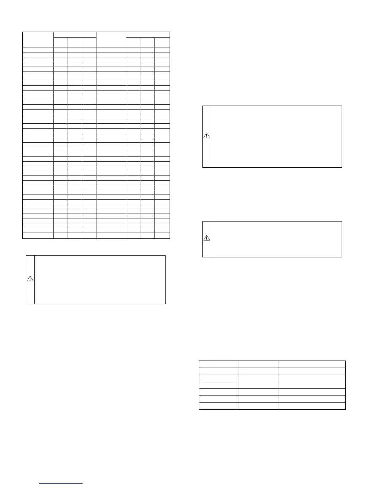
TABLE 12—GAS RATE (CU FT/HR)
SECONDS
FOR 1
REVOLUTION
SIZE OF TEST DIAL
SECONDS
FOR 1
REVOLUTION
SIZE OF TEST DIAL
1
Cu Ft
2
Cu Ft
5
Cu Ft
1
Cu Ft
2
Cu Ft
5
Cu Ft
10 360 720 1800 50 72 144 360
11 327 655 1636 51 71 141 355
12 300 600 1500 52 69 138 346
13 277 555 1385 53 68 136 340
14 257 514 1286 54 67 133 333
15 240 480 1200 55 65 131 327
16 225 450 1125 56 64 129 321
17 212 424 1059 57 63 126 316
18 200 400 1000 58 62 124 310
19 189 379 947 59 61 122 305
20 180 360 900 60 60 120 300
21 171 343 857 62 58 116 290
22 164 327 818 64 56 112 281
23 157 313 783 66 54 109 273
24 150 300 750 68 53 106 265
25 144 288 720 70 51 103 257
26 138 277 692 72 50 100 250
27 133 267 667 74 48 97 243
28 129 257 643 76 47 95 237
29 124 248 621 78 46 92 231
30
120 240 600 80 45 90 225
31 116 232 581 82 44 88 220
32 113 225 563 84 43 86 214
33 109 218 545 86 42 84 209
34 106 212 529 88 41 82 205
35 103 206 514 90 40 80 200
36 100 200 500 92 39 78 196
37 97 195 486 94 38 76 192
38 95 189 474 96 38 75 188
39 92 185 462 98 37 74 184
40 90 180 450 100 36 72 180
41 88 176 439 102 35 71 178
42 86 172 429 104 35 69 173
43 84 167 419 106 34 68 170
44 82 164 409 108 33 67 167
45 80 160 400 110 33 65 164
46 78 157 391 112 32 64 161
47 76 153 383 116 31 62 155
48 75 150 375 120 30 60 150
49 73 147 367 124 29 58 145
TABLE 13–SPEED SELECTION
COLOR SPEED AS SHIPPED
White Common C
OM
Black High Cool
Yellow Med-High SPARE
Orange† Med High-Gas Heat
Blue Med-Low Spare/High-Gas Heat
Red Low* Low-Gas Heat
* Continuous blower speed
† Available on 5-speed blowers only
—48—