6. Switching From Low- To High- Heat- If the furnace
control CPU switches from low-heat to high-heat, the
furnace control CPU will switch the inducer motor IDM
speed from low to high. The high-heat pressure switch relay
HPSR is de-energized to close the NC contact. When
sufficient pressure is available the high-heat pressure switch
HPS closes, and the high-heat gas valve solenoid GV-HI is
energized. The blower motor BLWM will switch to HI
HEAT speed five seconds after the furnace control CPU
switches from low-heat to high-heat.
7. Switching From High- To Low- Heat-The control CPU
will not switch from high-heat to low-heat while the
thermostat R-to-W circuit is closed when a single-stage
thermostat is used.
8. Blower-Off delay- When the thermostat is satisfied, the R
to W circuit is opened, de-energizing the gas valve GV-M,
stopping gas flow to the burners, and de-energizing the
humidifier terminal HUM. The inducer motor IDM will
remain energized for a 15-second post-purge period. The
blower motor BLWM and air cleaner terminal EAC-1 will
remain energized for 90, 120, 150, or 180 seconds (depend-
ing on selection at blower-OFF delay switches). The fur-
nace control CPU is factory-set for a 120-second blower-
OFF delay.
B. Two-Stage Heating With Two-Stage Thermostat
(Non-Adaptive Heating Mode)
(See Fig. 28 and 52A-G for thermostat connections).
NOTE: In this mode, the low-heat only switch must be ON to
select the low-heat only operation mode in response to closing the
thermostat R-to-W1 circuit. Closing the thermostat R-to-W1-
and-W2 circuits always causes high-heat operation, regardless of
the setting of the low-heat-only switch.
The wall thermostat ″calls for heat″, closing the R to W1 circuit for
low-heat or closing the R to W1 and-W2 circuits for high-heat. The
furnace control performs a self-check, verifies the low-heat and
high-heat pressure switch contacts LPS and HPS are open, and
starts the inducer motor IDM in high-speed.
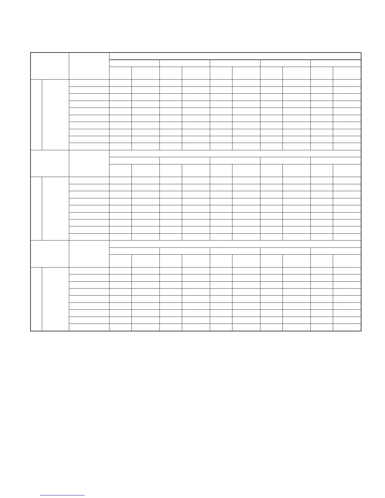
TABLE 10—MODEL 352MAV ORIFICE SIZE AND HIGH/LOW-HEAT MANIFOLD PRESSURE FOR CORRECT INPUT (CONT.)
FOR USE WITH 060 THROUGH 120 SIZE FURNACES ONLY
(TABULATED DATA BASED ON 20,000/13,000 BTUH PER BURNER, DERATED 2 PERCENT FOR EACH 1000 FT ABOVE SEA
LEVEL)*
ALTITUDE
RANGE
(FT)
AVG GAS
HEAT VALUE
(BTU/CU FT)
SPECIFIC GRAVITY OF NATURAL GAS
0.58 0.60 0.62 0.64 0.66
Orifice
no.
Manifold
Pressure
Orifice
no.
Manifold
Pressure
Orifice
no.
Manifold
Pressure
Orifice
no.
Manifold
Pressure
Orifice
no.
Manifold
Pressure
U.S.A. Only
7001
to
8000
15%
derate
625 43 3.8/1.6 42 3.3/1.4 42 3.4/1.4 42 3.5/1.5 42 3.6/1.5
650 43 3.5/1.5 43 3.7/1.6 43 3.8/1.6 42 3.2/1.4 42 3.3/1.4
675 44 3.8/1.6 43 3.4/1.4 43 3.5/1.5 43 3.6/1.5 43 3.7/1.6
700 44 3.5/1.5 44 3.6/1.5 44 3.8/1.6 43 3.4/1.4 43 3.5/1.5
725 44 3.3/1.4 44 3.4/1.4 44 3.5/1.5 44 3.6/1.5 44 3.7/1.6
750 45 3.7/1.6 45 3.8/1.6 44 3.3/1.4 44 3.4/1.4 44 3.5/1.5
775 45 3.5/1.5 45 3.6/1.5 45 3.7/1.6 45 3.8/1.6 44 3.3/1.4
800 45 3.3/1.4 45 3.4/1.4 45 3.5/1.5 45 3.6/1.5 45 3.7/1.6
825 47 3.6/1.5 45 3.2/1.3 45 3.3/1.4 45 3.4/1.4 45 3.5/1.5
850 47 3.4/1.4 47 3.5/1.5 47 3.7/1.5 45 3.2/1.3 45 3.3/1.4
ALTITUDE
RANGE
(FT)
AVG GAS
HEAT VALUE
(BTU/CU FT)
SPECIFIC GRAVITY OF NATURAL GAS
0.58 0.60 0.62 0.64 0.66
Orifice
no.
Manifold
Pressure
Orifice
no.
Manifold
Pressure
Orifice
no.
Manifold
Pressure
Orifice
no.
Manifold
Pressure
Orifice
no.
Manifold
Pressure
U.S.A. Only
Altitudes
8001
to
9000
17%
derate
600 43 3.8/1.6 42 3.3/1.4 42 3.4/1.4 42 3.5/1.5 42 3.6/1.5
625 43 3.5/1.5 43 3.6/1.5 43 3.8/1.6 42 3.2/1.4 42 3.3/1.4
650 44 3.7/1.6 43 3.4/1.4 43 3.5/1.5 43 3.6/1.5 43 3.7/1.6
675 44 3.5/1.5 44 3.6/1.5 44 3.7/1.6 44 3.8/1.6 43 3.4/1.5
700 44 3.2/1.4 44 3.3/1.4 44 3.4/1.5 44 3.6/1.5 44 3.7/1.6
725 45 3.6/1.5 45 3.8/1.6 44 3.2/1.4 44 3.3/1.4 44 3.4/1.4
750 45 3.4/1.4 45 3.5/1.5 45 3.6/1.5 45 3.8/1.6 44 3.2/1.4
775 45 3.2/1.3 45 3.3/1.4 45 3.4/1.4 45 3.5/1.5 45 3.6/1.5
800 47 3.6/1.5 47 3.7/1.6 45 3.2/1.3 45 3.3/1.4 45 3.4/1.4
ALTITUDE
RANGE
(FT)
AVG GAS
HEAT VALUE
(BTU/CU FT)
SPECIFIC GRAVITY OF NATURAL GAS
0.58 0.60 0.62 0.64 0.66
Orifice
no.
Manifold
Pressure
Orifice
no.
Manifold
Pressure
Orifice
no.
Manifold
Pressure
Orifice
no.
Manifold
Pressure
Orifice
no.
Manifold
Pressure
U.S.A. Only
9001
to
10,000
19%
derate
575 43 3.8/1.6 42 3.2/1.4 42 3.3/1.4 42 3.3/1.5 42 3.6/1.5
600 43 3.5/1.5 43 3.6/1.5 43 3.7/1.6 42 3.2/1.3 42 3.3/1.4
625 44 3.7/1.6 44 3.8/1.6 43 3.5/1.5 43 3.6/1.5 43 3.7/1.6
650 44 3.4/1.4 44 3.5/1.5 44 3.7/1.5 44 3.8/1.6 43 3.4/1.4
675 44 3.8/1.6 44 3.3/1.4 44 3.4/1.4 44 3.5/1.5 44 3.6/1.5
700 45 3.6/1.5 45 3.7/1.6 45 3.8/1.6 44 3.3/1.4 44 3.4/1.4
725 45 3.3/1.4 45 3.4/1.5 45 3.6/1.5 45 3.7/1.6 45 3.8/1.6
750 47 3.7/1.6 45 3.2/1.4 45 3.3/1.4 45 3.4/1.5 45 3.5/1.5
775 47 3.5/1.5 47 3.6/1.5 47 3.7/1.6 45 3.2/1.4 45 3.3/1.4
*Orifice numbers shown in shading are factory installed.
NOTE: Percents of derate are based on midpoint of U.S. altitude ranges.
—43—