C. Accessories
1. Electronic Air Cleaner (EAC)
Two male quick-connect terminals marked EAC-1 and
EAC-2 are provided for EAC connection. (See Fig. 32.)
These terminals are energized with 115-v (1.0-amp maxi-
mum) during blower motor operation.
2. Humidifier (HUM)
Connect an accessory 24 VAC, 0.5 amp maximum humidi-
fier (if used) to the 1/4-in. male quick-connect HUM
terminal and C
OM-24V screw terminal on the control board
thermostat strip. The HUM terminal is energized when gas
valve is energized. (See Fig. 31 or 32.)
NOTE: A field-supplied, 115–v controlled relay connected to
EAC terminals may be added if humidifier operation is desired
during blower operation.
CAUTION: UNIT DAMAGE HAZARD
Failure to follow this caution may result in unit compo-
nent damage.
DO NOT connect furnace control HUM terminal to HUM
(humidifier) terminal on Thermidistat™, Zone Controller
or similar device. See Thermidistat™, Zone Controller,
thermostat, or controller manufacturer’s instructions for
proper connection.
IX. DIRECT VENTING
The 352MAV furnaces require a dedicated (one 352MAV furnace
only) direct-vent system. In a direct-vent system, all air for
combustion is taken directly from outside atmosphere, and all flue
gases are discharged to outside atmosphere. The venting system
shall be installed in accordance to these instructions.
A. Removal of Existing Furnaces from
Common Vent Systems
When an existing Category I furnace is removed or replaced, the
original venting system may no longer be sized to properly vent
the remaining attached appliances. An improperly sized Category
I venting system could cause the formation of condensate in the
furnace and vent, leakage of condensate and combustion products,
and spillage of combustion products into the living space, etc.
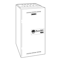
Fig. 28—Heating and Cooling Application Wiring Diagram 2-Stage Thermostat and Condensing Unit
A99072
115-V FUSED
DISCONNECT
SWITCH
(WHEN REQUIRED)
JUNCTION
BOX
CONTROL
BOX
24-V
TERMINAL
BLOCK
THREE-WIRE
HEATING-
ONLY
SEVEN
WIRE
2-STAGE THERMOSTAT TERMINALS
FIELD-SUPPLIED
FUSED DISCONNECT
2-SPEED
CONDENSING
UNIT
FURNACE
G
R
W2 Y2 G Y1
C
GND
GND
GND
GND
GND
GND
FIELD 24-V WIRING
FIELD 115-, 208/230-, 460-V WIRING
FACTORY 24-V WIRING
FACTORY 115-V WIRING
208/230- OR
460-V
THREE
PHASE
208/230-V
SINGLE
PHASE
Y2
Y1
C
WHT
BLK
WHT
BLK
W1 R
W2
COM
W/W1
Y/Y2
NOTES: 1. Connect Y-terminal as shown for proper operation.
2. Some thermostats require a "C" terminal connection as shown.
3. If any of the original wire, as supplied, must be replaced,
use same type or equivalent wire.
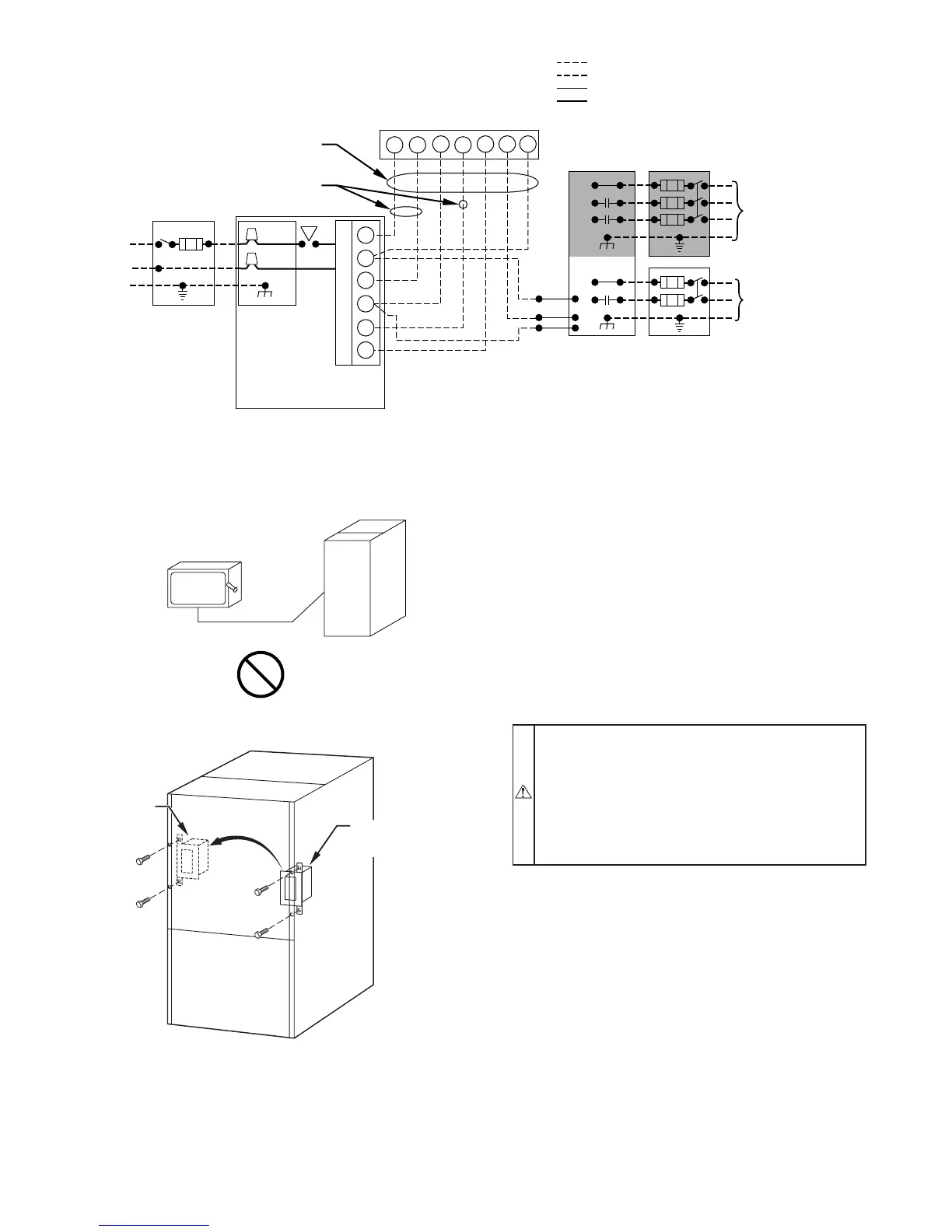
Fig. 29—Disconnect Switch and Furnace
A93033
COPPER
WIRE ONLY
ELECTRIC
DISCONNECT
SWITCH
ALUMINUM
WIRE
Fig. 30—Relocating J-Box
A00212
FACTORY
INSTALLED
LOCATION
ALTERNATE
FIELD
LOCATION
—22—