4. Insert assembled combustion air inlet pipe into intake
housing as shown in Fig. 37.
5. Drill a 1/8-in. hole in 2-in, combustion air pipe using the
hole in intake housing as a guide.
6. Install a field-supplied No. 6 or No. 8 sheet metal screw into
combustion air pipe.
7. Install casing hole filler cap (factory-supplied in loose parts
bag) in unused combustion air pipe casing hole.
NOTE: Do not attach combustion air intake pipe permanently to
combustion air intake housing since it may be necessary to remove
pipe for service of igniter or flame sensor.
ATTACHMENT OF COMBUSTION AIR INTAKE HOUSING
PLUG FITTING
The combustion-air intake plug fitting must be installed in unused
combustion air intake housing. This fitting must be attached by
using RTV sealant, or by drilling a 1/8-in. hole in fitting, using
hole in intake housing as a guide. Install a field-supplied No. 6 or
No. 8 sheet metal screw.
NOTE: DO NOT OVERTIGHTEN SCREW. Breakage of intake
housing or fitting may cause air leakage to occur.
A plugged drain connection has been provided on this fitting for
use when moisture is found in combustion air intake pipe and
combustion box. If use of this drain connection is desired, drill out
fitting’s tap plug with 3/16-in. drill and connect a field-supplied
3/8-in. tube. This tube should be routed to open condensate drain
for furnace and A/C (if used), and should be trapped, as shown in
Fig. 40.
NOTE: (Direct Vent/2-Pipe System ONLY) Moisture in combus-
tion air intake may be a result of improper termination. Ensure
combustion air pipe termination is similar to those as shown in Fig.
40 so that it will not be susceptible to area where light snow or
others sources of moisture could be pulled in.
F. Vent Pipe
GENERAL
Furnace vent connection must be attached as shown in Fig. 37.
WARNING: CARBON MONOXIDE POISONING
AND PROPERTY DAMAGE HAZARD
Failure to follow this warning could result in property
damage, personal injury, or death.
Vent pipes must be airtight.
NOTE: A 2-in. diameter pipe must be used within the furnace
casing. Make all pipe diameter transitions outside furnace casing
per Fig. 39.
The minimum vent pipe length for these furnaces is 5 ft. Short pipe
lengths (5-8 ft) may discharge condensate droplets. These conden-
sate droplets may be undesirable. A 12-in. minimum offset pipe
section is recommended to reduce excessive condensate droplets
from exiting vent pipe outlet. (See Fig. 41)
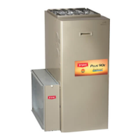
Fig. 37—Combustion-Air and Vent Pipe
Connections
A05092
COMBUSTION-
AIR
COMBUSTION-
AIR
AIR
FLOW
VENT
VENT
VENT
AIR
FLOW
AIR
FLOW
AIR
FLOW
UPFLOW DOWNFLOW
HORIZONTAL-LEFT DISCHARGE HORIZONTAL-RIGHT DISCHARGE
Select 1 vent pipe connection and
1 combustion-air pipe connection.
COMBUSTION-
AIR
COMBUSTION-
AIR
COMBUSTION-
AIR
COMBUSTION-
AIR
VENT
VENT
VENT
NOTE: Select 1 vent pipe connection and
1 combustion-air pipe connection.
NOTE:
* For Non-Direct Vent (1-Pipe) system, orient elbow so that its
opening faces down.
** For Non-Direct Vent (1-Pipe) system, orient elbow so that its
opening faces sideways.
† An external trap kit (see furnace product data sheet) must be used.
*
*
**
**
†
†
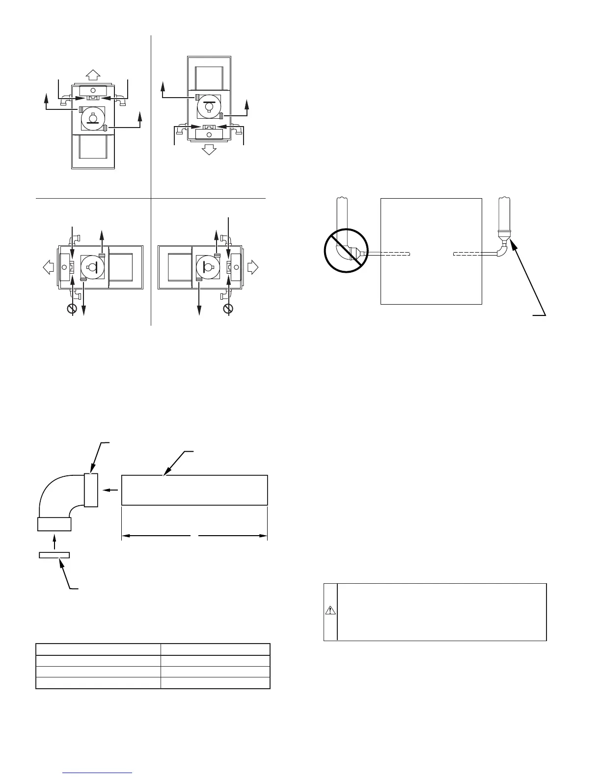
Fig. 38—Combustion-Air Inlet Pipe Assembly
LENGTH OF STRAIGHT PIPE PORTION OF
COMBUSTION-AIR INLET PIPE ASSEMBLY (IN.)
CASING WIDTH A
17-1/2 8-1/2 ± 1/2
21 10-1/2 ± 1/2
24-1/2 12 ± 1/2
A96211
FIELD-SUPPLIED
2-IN. DIAMETER
PVC PIPE
FIELD-SUPPLIED
2-IN. DIAMETER
PVC 90° ELBOW
COMBUSTION-AIR DISC
(FACTORY-SUPPLIED IN
LOOSE PARTS BAG)
A
Fig. 39—Combustion-Air and Vent Pipe Diameter
Transition Location and Elbow Configuration
A93034
FURNACE
PIPE DIAMETER
TRANSITION IN
VERTICAL SECTION
NOT IN
HORIZONTAL
SECTION
—34—
→
→