6
construction process must be either changed or thoroughly
cleaned prior to occupancy.
S The furnace, ductwork and filters are cleaned as necessary to
remove drywall dust and construction debris from all HVAC
system components after construction is completed.
S After construction is complete, verify furnace operating
conditions including ignition, input rate, temperature rise and
venting, according to the manufacturer’s instructions. If this
furnace is installed with a direct--vent (combustion air and flue)
system, a factory accessory termination kit must be installed. In a
direct--vent system, all air for combustion is taken directly from
the outside atmosphere. See furnace and factory accessory
termination kit instructions for proper installation.
S These furnaces are shipped with the following materials to assist
in proper furnace installation. These materials are shipped in the
main blower compartment.
Installer Packet Includes:
Installation, Start---up, and Operating Instructions
Service and Maintenance Instructions
User’s Information Manual
Warranty Certificate
Loose Parts Bag includes: Quantity
Pressure tube extension 1
Collector Box or condensate trap extension tube 1
Inducer Housing drain tube 1
1/2--- in. (13 mm) CPVC street elbow 2
Drain tube coupling 1
Drain tube coupling grommet 1
Gas line grommet 1
Vent pipe grommet 1
Combustion--- air pipe grommet 2
Gas line entry hole filler plug 1
Power entry hole filler plug 2
Condensate trap hole filler plug 3
Vent and combustion ---air intake hole filler plug 2
Combustion--- air pipe perforated disk assembly 1
S The furnace shall be installed so that the electrical components
are protected from water.
S For accessory installation details, refer to applicable installation
literature.
CODES AND STANDARDS
Follow all national and local codes and standards in addition to
these instructions. The installation must comply with regulations of
the serving gas supplier, local building, heating, plumbing, and
other codes. In absence of local codes, the installation must comply
with the national codes listed below and all authorities having
jurisdiction in Canada.
In the United States and Canada, follow all codes and standards for
the following:
Step 1 — Safety
S US: National Fuel Gas Code (NFGC) NFPA 54--2006/ANSI
Z223.1-- 2006 and the Installation Standards, Warm Air Heating
and Air Conditioning Systems ANSI/NFPA 90B
S CANADA: Natio nal Standard of Canad a, Natural Gas and
Propane Installation Code (NSCNGPIC) CAN/CSA B149.1-- 05
Step 2 — General Installation
S US: NFGC and the NFPA 90B. For copies, contact the National
Fire Protection Association Inc., Batterymarch Park, Quincy ,
MA 02269; or for only the NFGC contact the American Gas
Association, 400 N. Capitol, N.W., Washington DC 20001
S CANADA: NSCNGPIC. For a copy, contact Standard Sales,
CSA International, 178 Rexdale Boulevard,
Step 3 — Combustion and Ventilation Air
S NFPA 54-- 2006/ANSI Z223.1--2006, Air for Combustion and
Ventilation
S CANADA: Part 8 of the NSCNGPIC CAN/CSA B149.1 --05,
Venting Systems and Air Supply for Appliances
Step 4 — Duct Systems
S US and CANADA: Air Conditioning Contractors Association
(ACCA) Manual D, Sheet Metal and Air Conditioning
Contractors National Association (SMACNA), or American
Society of Heating, Refrigeration, and Air Conditioning
Engineers (ASHRAE) 2005 Fundamentals Handbook Chapter
35.
Step 5 — Acoustical Lining and Fibrous Glass
Duct
S US and CANADA: current edition of SMACNA, NFPA 90B as
tested by UL Standard 181 for Class I Rigid Air Ducts
Step 6 — Gas Piping and Gas Pipe Pressure
Testing
S US: NFGC; chapters 5, 6, 7, and 8 and national plumbing codes
S CANADA: NSCNGPIC Parts 4, 5, 6 and 9. In the state of
Massachusetts:
S This product must be installed by a licensed plumber or gas
fitter.
S When flexible connectors are used, the maximum length shall
not exceed 36 inches.
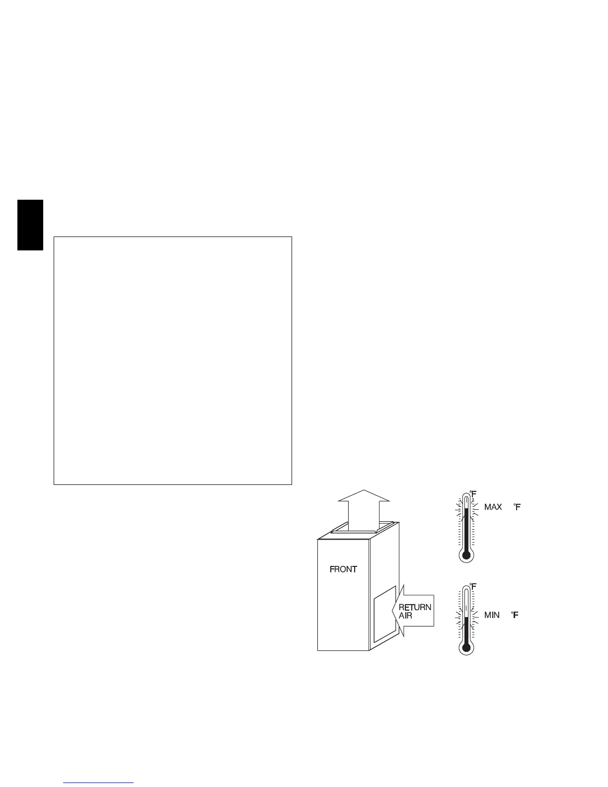
60
80 / 27 C
/ 16 C
A06745
Fig. 4 -- Return--Air Temperature
355A