9
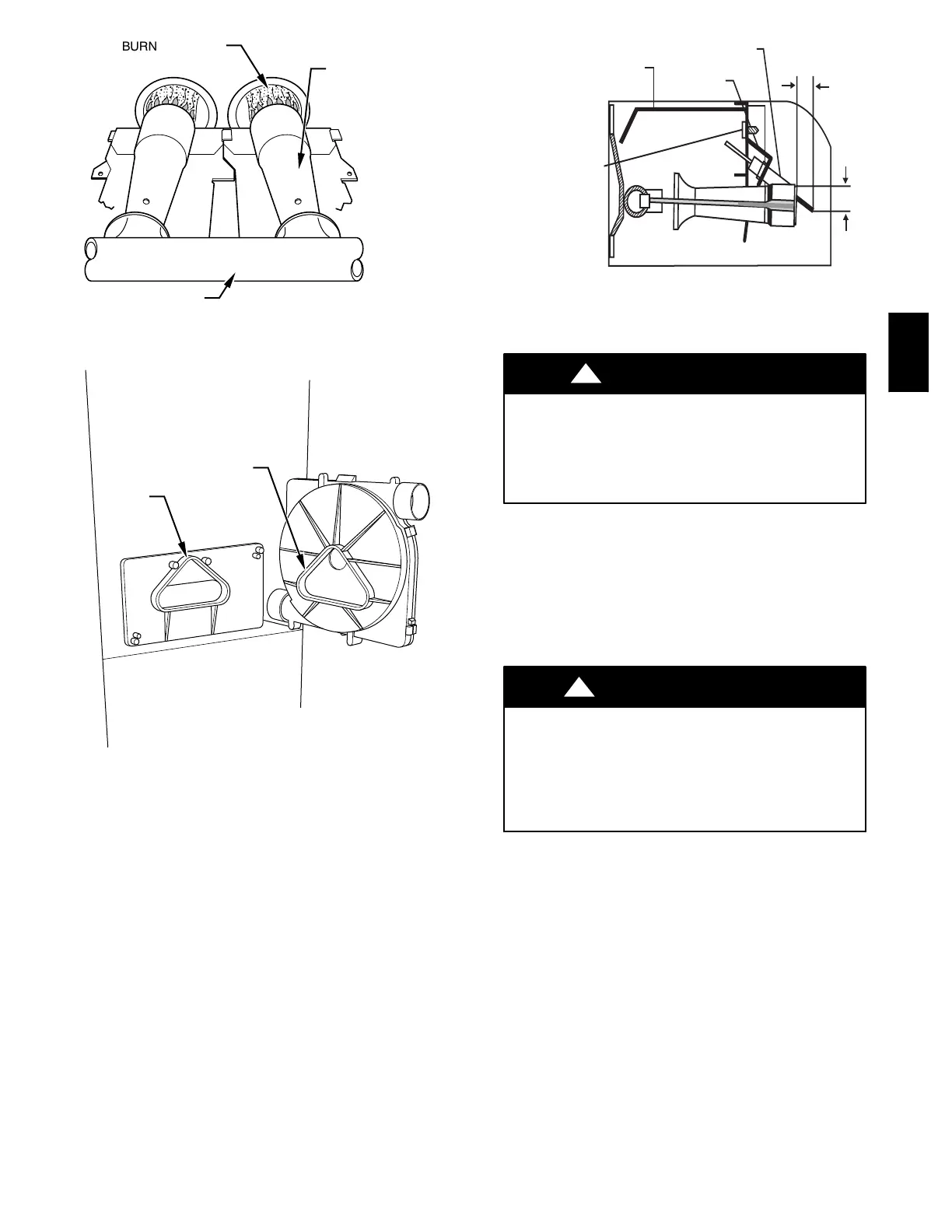
BURNER FLAME
BURNER
MANIFOLD
A89020
Fig. 11 --- Burner Flame
RTV
PAM
A93081
Fig. 12 --- Gasket on Collector Box
BRACKET
IGNITER
9/16˝
11/16˝
EXTENDED IGNITER
BRACKET HANDLE
IGNITER BRACKET
MOUNTING SCREW
A05075
Fig. 13 --- Igniter Bracket
UNIT DAMAGE HAZARD
Failure to follow this caution may result in premature
failure of the igniter.
The igniter is fragile. DO NOT allow it to hit burner box
parts while removing or replacing it.
CAUTION
!
e. If replacement is required, replace igniter on igniter
bracket and then install assembly into burner box to
avoid damage to the igniter.
6. To replace igniter and bracket assembly, reverse items 5a
through 5d.
7. Reconnect igniter wire connection and insert the igniter
wires in the slot in the manifold grommet, dressing the ig-
niter wires to ensure there is no tension on the igniter it-
self. (See Fig.7.)
ELECTRICAL SHOCK HAZARD
Failure to follow this warning could result in electrical
shock, personal injury, or death.
Igniter wires must be securely placed in slot in manifold
grommet or else they could become pinched or severed
and electrically shorted.
!
WARNING
8. Reinstall burner box cover.
9. Turn on gas and electrical supplies to furnace.
10. Verify igniter operation by initiating control board self--
test feature or by cycling thermostat.
11. If furnace failes to ignite properly, verify position of igni-
ter (See Fig. 14) by removing the burner box assembly ac-
cording to instructions in Step 4. After verifying and/or
adjusting the location, re--install the burner box assembly
according to the instructions in Step 4. Repeat igniter op-
eration test in item 10.
12. Replace main furnace door.
Step 7—Electrical Controls and Wiring
355BAV
 Loading...


