Recognize safety information. This is the safety-alert symbol .
When you see this symbol on the furnace and in instructions or
manuals, be alert to the potential for personal injury.
Understand the signal words DANGER, WARNING, and CAU-
TION. These words are used with the safety-alert symbol. DAN-
GER identifies the most serious hazards which will result in severe
personal injury or death. WARNING signifies a hazard which
could result in personal injury or death. CAUTION is used to
identify unsafe practices which would result in minor personal
injury or product and property damage.
These instructions cover minimum requirements and conform to
existing national standards and safety codes. In some instances,
these instructions exceed certain local codes and ordinances,
especially those that may not have kept up with changing residen-
tial construction practices. We require these instructions as a
minimum for a safe installation.
ELECTROSTATIC DISCHARGE (ESD) PRECAUTIONS
PROCEDURE
CAUTION: Electrostatic discharge can affect electronic
components. Take precautions during furnace installation
and servicing to protect the furnace electronic control.
Precautions will prevent electrostatic discharges from
personnel and hand tools which are held during the
procedure. These precautions will help to avoid exposing
the control to electrostatic discharge by putting the
furnace, the control, and the person at the same electro-
static potential.
1. Disconnect all power to the furnace. DO NOT TOUCH
THE CONTROL OR ANY WIRE CONNECTED TO THE
CONTROL PRIOR TO DISCHARGING YOUR BODY’S
ELECTROSTATIC CHARGE TO GROUND.
2. Firmly touch a clean, unpainted, metal surface of the
furnace chassis which is close to the control. Tools held in
a person’s hand during grounding will be satisfactorily
discharged.
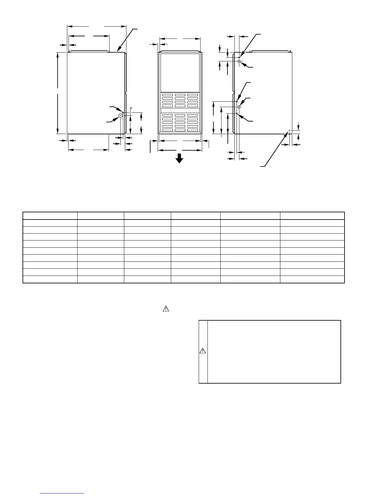
TABLE 2—DIMENSIONS (IN.)
UNIT SIZE A D E VENT CONN SHIP. WT (LB)
024050 14-3/16 12-9/16 12-11/16 4 124
036050 14-3/16 12-9/16 12-11/16 4 127
024070 14-3/16 12-9/16 12-11/16 4 141
036070 14-3/16 12-9/16 12-11/16 4 145
036095 17-1/2 15-7/8 16 4 154
048095 17-1/2 15-7/8 16 4 154
048115 17-1/2 15-7/8 16 4 171
048115 21 19-3/8 19-1/2 4 181
060135 24-1/2 22-7/8 23 5 192
Fig. 1—Dimensional Drawing
A88324
4
3
⁄
16
″
2″
2
15
⁄
16
″
13
⁄
16
″
11
⁄
16
″
9
1
⁄
8
″
10
1
⁄
4
″
1
1
⁄
16
″
2
1
⁄
8
″
8
1
⁄
4
″
10
1
⁄
4
″
1
1
⁄
16
″
2
1
⁄
8
″
16
1
⁄
16
″
13
5
⁄
16
″
19″
11
⁄
16
″
13
⁄
16
″
11
⁄
16
″
20″
28
1
⁄
2
″
39
7
⁄
8
″
D
5
⁄
8
″ TYP
1
″ TYP
E
A
AIRFLOW
OUTLET
INLET
1
⁄
2
″ DIA
THERMOSTAT
WIRE ENTRY
7
⁄
8
″ DIA
ACCESSORY
7
⁄
8
″ DIA
ACCESSORY
DIMPLES TO DRILL HOLES
FOR HANGER BOLTS (4 PLACES)
IN HORIZONTAL POSITION
ADDITIONAL
7
⁄
8
″ DIA K.O. ARE
LOCATED IN THE TOP PLATE
AND BOTTOM PLATE
NOTE:
7
⁄
8
″ DIA HOLE
POWER ENTRY
1
1
⁄
2
″ DIA
R.H. GAS ENTRY
7
⁄
8
″ DIA
ACCESSORY
1
3
⁄
4
″ DIA HOLE
GAS ENTRY
VENT CONNECTION
—2—