CAUTION: Do not connect aluminum wire between
disconnect switch and furnace. Use only copper wire.
Make all electrical connections in accordance with the current
edition of the National Electrical Code (NEC) ANSI/NFPA
70-1993, and any local codes or ordinances that might apply. For
Canadian installations, all electrical connections must be made in
accordance with Canadian Electrical Code CSA C22.1, or authori-
ties having jurisdiction.
NOTE: Proper polarity must be maintained for 115-v wiring. If
polarity is incorrect, control board fault code indicator light will
flash rapidly and furnace will not operate.
WARNING: The cabinet MUST have an uninterrupted
or unbroken ground according to NEC ANSI/NFPA
70-1990 and Canadian Electrical Code CSA C22.1 or
local codes to minimize personal injury if an electrical
fault should occur. This may consist of electrical wire or
conduit approved for electrical ground when installed in
accordance with existing electrical codes. Do not use gas
piping as an electrical ground. Failure to follow this
warning could result in electrical shock, fire, or death.
B. 24-v Wiring
Make field 24-v connections at the 24-v terminal strip. (See Fig.
11.) Connect terminal Y as shown in Fig. 12 for proper operation
in cooling mode. Use AWG No. 18 color-coded wire only.
The 24-v circuit contains an automotive-type, 3-amp fuse located
on the main control board. Any direct shorts during installation,
service, or maintenance could cause this fuse to blow. If fuse
replacement is required, use ONLY a 3-amp fuse of identical size.
C. Accessories
1. Electronic air cleaner (EAC)
Two quick-connect terminals marked EAC-1 and EAC-2,
are provided for EAC connection. (See Fig. 9.) These
terminals are energized with 115v (1.5-amp maximum)
during blower motor operation.
2. Humidifier (HUM)
Quick-connect terminal HUM and screw terminal Com are
provided for 24-v humidifier connection. The terminals are
energized with 24v (0.5-amp maximum) after inducer
motor prepurge period.
NOTE: A field-supplied, 115-v controlled relay connected to
EAC terminals may be added if humidifier operation is desired
during blower operation.
IX. VENTING
Refer to the enclosed Installation Instructions, GAMA Venting
Tables for Category I Furnaces and Venting Tables for Category I
Fan-Assisted Furnaces. The horizontal portion of the venting
system shall maintain a minimum of 1/4-in. upward slope per
linear ft and it shall be rigidly supported every 5 ft or less with
hangers or straps to ensure that there will be no movement after
installation.
X. START-UP, ADJUSTMENT, AND SAFETY CHECK
A. General
NOTE: Proper polarity must be maintained for 115-v wiring. If
polarity is incorrect, control board fault indicator light will flash
rapidly and furnace will not operate.
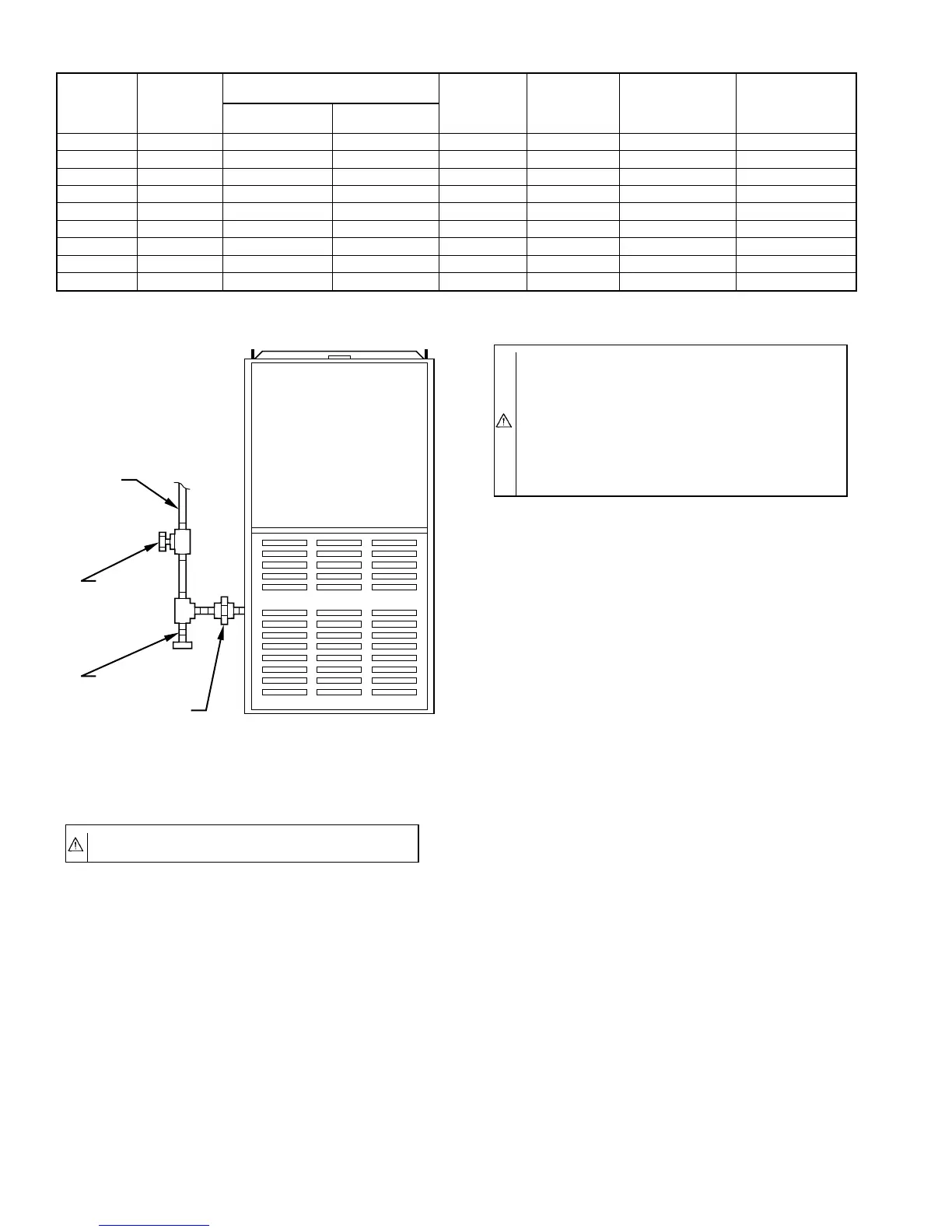
TABLE 6—ELECTRICAL DATA
UNIT SIZE
VOLTS—
HERTZ—
PHASE
OPERATING VOLTAGE RANGE
MAXIMUM
UNIT AMPS
MINIMUM
WIRE GAGE
MAXIMUM WIRE
LENGTH FT‡
MAXIMUM
FUSE OR HACR-
TYPE CKT BKR
AMPS†
Maximum* Minimum*
024050 115—60—1 127 104 6.6 14 42 15
036050 115—60—1 127 104 8.1 14 34 15
024070 115—60—1 127 104 6.7 14 42 15
036070 115—60—1 127 104 8.4 14 33 15
036095 115—60—1 127 104 9.2 14 30 15
048095 115—60—1 127 104 10.2 14 28 15
048115 115—60—1 127 104 10.1 14 28 15
060115 115—60—1 127 104 13.3 12 33 20
060135 115—60—1 127 104 14.3 12 31 20
* Permissible limits of the voltage range at which the unit will operate satisfactorily.
† Time-delay fuse is recommended.
‡ Length shown is as measured 1 way along wire path between unit and service panel for maximum 2 percent voltage drop.
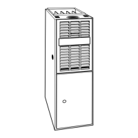
Fig. 10—Typical Gas Pipe Arrangement
A89414
GAS
SUPPLY
MANUAL
SHUTOFF
VALVE
SEDIMENT
TRAP
UNION
—8—
→
→