the % voltage imbalance. Operation on improper line volt-
age or excessive phase imbalance constitutes abuse and
may cause damage to electrical components. Such op-
eration would invalidate any applicable warranty.
5. Insulate low-voltage wires for highest voltage con-
tained within conduit when low-voltage control wires are
run in same conduit as high-voltage wires.
6. Do not damage internal components when drilling through
any panel to mount electrical hardware, conduit, etc.
High-Voltage Connections (Fig. 9)
The unit must have a separate electrical service with a field-
supplied, waterproof, fused disconnect switch mounted at, or
within sight from, the unit. Refer to the unit rating plate for
maximum fuse/circuit breaker size and minimum circuit amps
(ampacity) for wire sizing.
The field-supplied disconnect switch may be mounted on the
unit over the high-voltage inlet hole in the control corner panel.
Proceed as follows to complete the high-voltage connections
to the unit:
1. Connect ground lead to chassis ground connection when
using separate ground wire.
2. Pigtails are provided for field power connection. Use
factory-supplied splices or copper/aluminum connector.
Install conduit connectors in side panel power supply
knockout openings indicated in Fig. 3. Route power lines
through connector to unit control box.
3. For units with electric heat, refer to Table 3 to deter-
mine appropriate power wiring figure (Fig. 12 - 14), and
route power lines as indicated in appropriate figure. A
single point kit must be used with all heater packages.
See Fig. 12 - 14 for single point kit/electric heater
combinations.
Table 2 — American/European Wire Conversions
AMERICAN EUROPEAN
Industry Standard American Conversion Industry Standard
Size (mm
2
) Size (mm
2
)
18 AWG 0.82 1.0
16 AWG 1.30 1.5
14 AWG 2.08 2.5
12 AWG 3.30 4.0
10 AWG 5.25 6.0
8AWG 6.36 10.0
6AWG 13.29 16.0
4AWG 21.14 25.0
3AWG 26.65 —
2AWG 33.61 35.0
1AWG 42.39 50.0
1/0 AWG 53.49 —
2/0 AWG 67.42 70.0
3/0 AWG 85.00 95.0
4/0 AWG 107.19 120.0
250 Kcmil 126.64 150.0
300 Kcmil 151.97 —
350 Kcmil 177.90 185.0
400 Kcmil 202.63 240.0
500 Kcmil 253.29 300.0
600 Kcmil 303.95 —
LEGEND
AWG — American Wire Gage
Kcmil — Thousand Circular Mils
LEGEND
BAT — Battery OFC — Outdoor-Fan Contactor
C—Contactor P—Plug
CB — Circuit Breaker TB — Terminal Board
DAT — Discharge-Air Thermistor TRAN — Transformer
EMC/EMFC — Energy Management Closed
Field Wiring
EMO/EMFO — Energy Management Open
EQUIP — Equipment
Factory Wiring
GND — Ground
HR — Heater Relay
Splice Connection (Factory Supplied)
IFC — Indoor-Fan Contactor
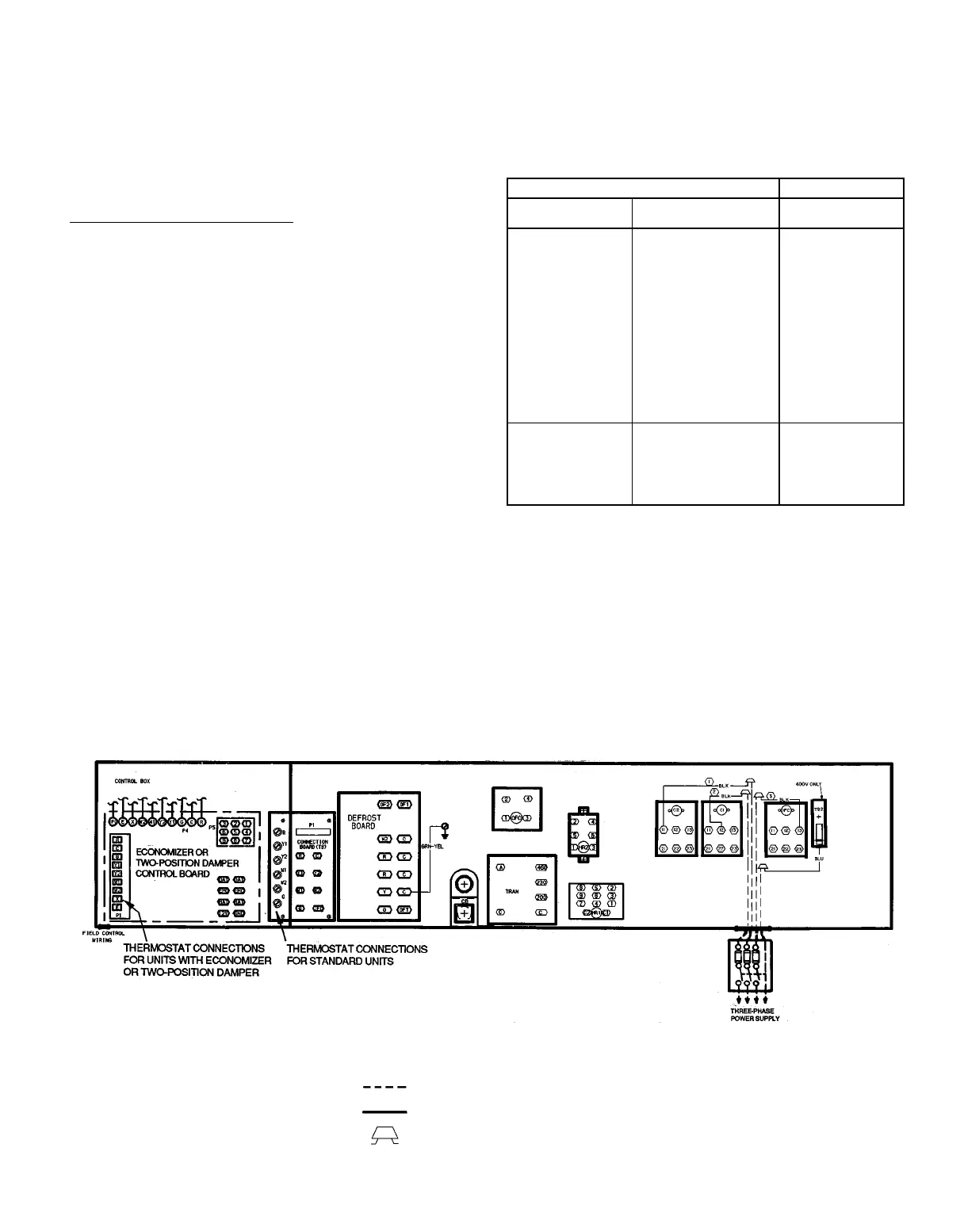
Fig. 9 — Field Wiring Connections
—9—
 Loading...