—10—
Table 3A — Refrigerant Piping Sizes —
569D, 576C, 569F Units
LEGEND
L—Liquid Line S—Suction Line
*Field-supplied suction accumulator required.
NOTES:
1. Pipe sizes are based on a 2 F (1 C) loss for liquid and suction lines.
2. Pipe sizes are based on the maximum linear length, shown for each
column, plus a 50% allowance for fittings.
3. Charge units with R-22 in accordance with unit installation instructions.
Table 3B — Refrigerant Piping Sizes —
566D Units
LEGEND
Close-coupled
*Field-supplied suction accumulator required.
†Requires a double suction riser if 2 unloaders are used and the evaporator is
below the condensing unit. See Table 4 and Fig. 6 for more information.
NOTES:
1. Pipe sizes are based on a 2 F (1.1 C) loss for liquid lines and a 1.5 F
(0.8 C) loss for suction lines.
2. Pipe sizes are based on an equivalent length equal to the maximum
length of interconnecting piping plus 50% for fittings. A more accurate
estimate may result in smaller sizes.
3. For applications with refrigerant line lengths greater than 100 ft, contact
Bryant representative.
Table 3C — Refrigerant Piping Sizes —
566E Units
LEGEND
*Field-supplied suction accumulator required.
NOTES:
1. Pipe sizes are based on a 2 F (1.1 C) loss for liquid lines and a 1.5 F
(0.8 C) loss for suction lines.
2. Pipe sizes are based on an equivalent length equal to the maximum
length of interconnecting piping plus 50% for fittings. A more accurate
estimate may result in smaller sizes.
3. For applications with refrigerant line lengths greater than 100 ft, contact
Bryant representative.
Table 4 — Refrigerant Piping Sizes, Double Suction
Risers — 566D150, 180 Units
NOTES:
1. See Fig. 5 for “A,” “B,” and “C” dimensions.
2. No double suction risers are needed for unit size 240.
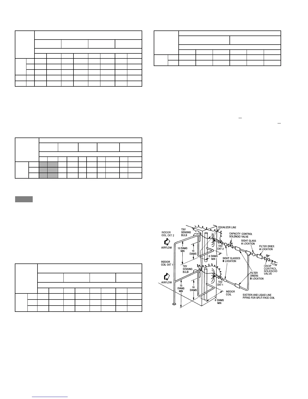
B. Install Filter Drier(s) and Moisture Indicator(s)
Every unit should have a filter drier and liquid-moisture
indicator (sight glass). Refer to Table 5. In some applications,
depending on space and convenience requirements, it may be
desirable to install 2 filter driers and sight glasses. One filter
drier and sight glass may be installed at A
locations in Fig. 7,
or, 2 filter driers and sight glasses may be installed at B
locations.
Select the filter drier for maximum unit capacity and mini-
mum pressure drop. Complete the refrigerant piping from
indoor unit to outdoor unit before opening the liquid and
suction lines at the outdoor unit.
C. Install Liquid Line Solenoid Valve — Solenoid Drop
It is recommended that a solenoid valve be placed in the
main liquid line (see Fig. 7) between condensing unit and fan
coil. Refer to Table 5. (A liquid line solenoid valve is required
when the liquid line length exceeds 75 ft.) This valve
prevents refrigerant migration (which causes oil dilution) to
the compressor during the off cycle at low outdoor ambient
temperatures. The solenoid should be wired in parallel with
the compressor contactor coil. This means of electrical
control is referred to as solenoid drop control.
UNIT
LINEAR LENGTH OF INTERCONNECTING PIPING —
FT (m)
0-25
(0-7.5)
26-50
(7.8-15)
51-75
(15.3-23)
76-100*
(23.3-30)
Line Size (in. OD)
LSLSLSLS
569D
072
3
/
8
1
1
/
8
3
/
8
1
1
/
8
3
/
8
1
1
/
8
3
/
8
1
1
/
8
090
3
/
8
1
1
/
8
3
/
8
1
1
/
8
3
/
8
1
1
/
8
3
/
8
1
1
/
8
120
1
/
2
1
3
/
8
1
/
2
1
3
/
8
1
/
2
1
3
/
8
1
/
2
1
3
/
8
576C
120
1
/
2
1
3
/
8
1
/
2
1
3
/
8
1
/
2
1
3
/
8
1
/
2
1
3
/
8
569F 120 (2)
3
/
8
(2) 1
1
/
8
(2)
3
/
8
(2) 1
1
/
8
(2)
3
/
8
(2) 1
1
/
8
(2)
3
/
8
(2) 1
1
/
8
UNIT
LENGTH OF INTERCONNECTING PIPING, FT (M)
0-15
(0-4.5)
16-25
(4.8-7.5)
26-50
(7.8-15)
51-75
(15.3-23)
76-100*
(23.3-30)
Line Size (in. OD)
LSLSLSLSLS
566D
150
1
/
2
1
1
/
8
1
/
2
1
3
/
8
5
/
8
1
3
/
8
5
/
8
1
5
/
8
†
5
/
8
1
5
/
8
†
180
1
/
2
1
3
/
8
5
/
8
1
3
/
8
5
/
8
1
5
/
8
7
/
8
1
5
/
8
7
/
8
2
1
/
8
†
240
5
/
8
1
5
/
8
5
/
8
1
5
/
8
7
/
8
1
5
/
8
7
/
8
2
1
/
8
7
/
8
2
1
/
8
L—Liquid
S—Suction
UNIT
LINEAR LENGTH OF INTERCONNECTING PIPING
FT (M)
0-25
(0-7.5)
26-50
(7.8-15)
51-75
(15.3-23)
76-100*
(23.3-30)
Line Size (in. OD)
LSLSLSLS
566E
150
1
/
2
1
1
/
8
1
/
2
1
1
/
8
1
/
2
1
1
/
8
1
/
2
1
3
/
8
180
1
/
2
1
3
/
8
1
/
2
1
3
/
8
1
/
2
1
3
/
8
5
/
8
1
3
/
8
240
1
/
2
1
3
/
8
1
/
2
1
3
/
8
5
/
8
1
3
/
8
5
/
8
1
3
/
8
L—Liquid
S—Suction
UNIT
LENGTH OF INTERCONNECTING PIPING, FT (M)
50-75
(15-23)
76-100
(23.3-30)
Line Size (in. OD)
ABCABC
566D
150 1
1
/
8
1
3
/
8
1
5
/
8
1
1
/
8
1
3
/
8
1
5
/
8
180 ———1
3
/
8
1
5
/
8
2
1
/
8
LEGEND
TXV — Thermostatic Expansion Valve
Fig. 7 — Location of Sight Glass(es)
and Filter Driers
 Loading...