—20—
NOTE: The crankcase will be slightly pressurized. Do not
remove the plug, or the entire oil charge will be lost.
Small amounts of oil can be removed through the oil pump
discharge connection while the compressor is running.
C. Start Unit
The field disconnect is closed, the fan circuit breaker is
closed, and the space thermostat is set above ambient so that
there is no demand for cooling. Only the crankcase heater
will be energized.
Next, close the compressor circuit breaker and then reset
space thermostat below ambient so that a call for cooling is
ensured.
NOTE: Do not use circuit breaker to start and stop the com-
pressor except in an emergency.
After starting, there is a delay of at least 3 seconds before
compressor starts.
D. Adjust Refrigerant Charge
Unit must be charged in Cooling mode only. Refer to Cooling
Charging Charts, Fig. 14-18 and to Table 7 for maximum
charge level. Vary refrigerant until the conditions of the
chart are met. Note that charging charts are different from
type normally used. Charts are based on charging the units
to the correct subcooling for the various operating conditions.
Accurate pressure gage and temperature sensing device are
required. Connect the pressure gage to the service port on
the liquid line service valve. Mount the temperature sensing
device on the liquid line, close to the liquid line service valve
and insulate it so that outdoor ambient temperature does not
affect the reading. Indoor airflow must be within the normal
operating range of the unit. Operate unit a minimum of
15 minutes. Ensure pressure and temperature readings have
stabilized. Plot liquid pressure and temperature on chart
and add or reduce charge to meet curve. Adjust charge to
conform with charging chart, using the liquid pressure and
temperature to read chart.
If the sight glass is cloudy, check refrigerant charge again.
Ensure all fans are operating. Also ensure maximum allow-
able liquid lift has not been exceeded. If charged per chart
and if the sight glass is still cloudy, check for a plugged filter
drier or a partially closed solenoid valve. Replace or repair,
as needed.
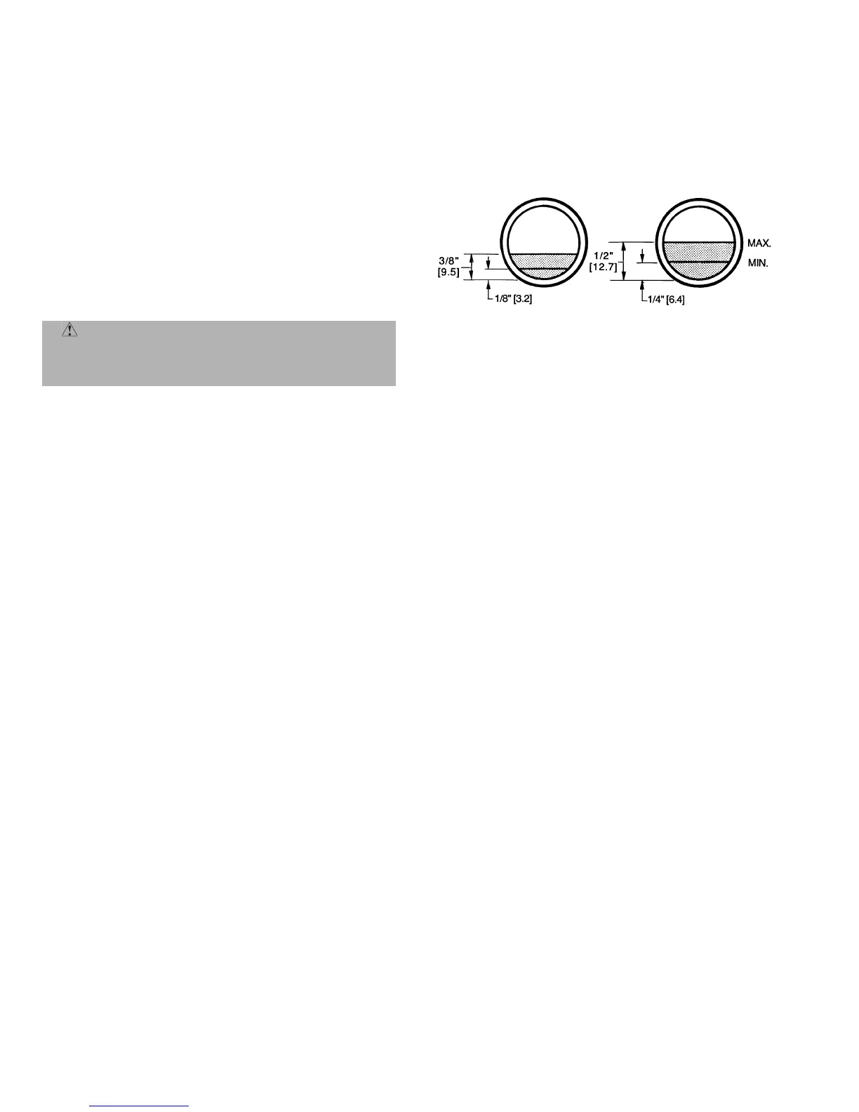
E. Check Compressor Oil Level
After adjusting the refrigerant charge, allow the compressor
to run fully loaded for 20 minutes. Running oil level should
be within view of the crankcase sight glass. Stop the com-
pressor at the field power supply disconnect and check the
crankcase oil level. Add oil only if necessary to bring the oil
into view in the sight glass. If oil is added, run the compres-
sor for an additional 10 minutes, then stop and check oil
level. If the level remains low, check the piping system for
proper design for oil return; also, check the system for leaks.
If the initial check shows too much oil (too high in the sight
glass) remove oil to proper level. See Preliminary Oil
Charge, this page, for proper procedure for adding and
removing oil. See Fig. 19.
When the above checks are complete, repeat the procedure
with the unit operating at minimum load conditions.
Unload the compressor by turning the control set point
adjustment nut counterclockwise until the adjustment nut
stops. The unloader is now at 0 psig set point. If electric actu-
ated unloaders are installed, energize the solenoid to unload
the compressor.
Return unloader to original setting after checks are complete.
F. Final Checks
Ensure all safety controls are operating, control panel covers
are on, and the service panels are in place.
OPERATING SEQUENCE
I. COOLING
A. 569D072-120, 576C090-120 Cooling
At start-up, the thermostat calls for cooling. With all safety
devices satisfied, the compressor contactor and fan contactor
energize, causing the compressor and outdoor-fan motor to
operate. Contacts energize, allowing the field-supplied and
field-installed indoor-fan contactor to function. A field-
supplied and field-installed liquid line valve also opens,
allowing the system to function in Cooling mode. As cooling
demand is satisfied, the thermostat contacts break, deener-
gizing the contactor and causing the system to shut off. The
liquid line solenoid valve closes, minimizing the potential for
refrigerant migration. The compressor does not restart until
the thermostat again calls for cooling. The system is pro-
tected with a safety circuit so that the system will not start if
a fault exists (i.e., high-pressure or discharge gas tempera-
ture [569D090 and 120 only] fault). To reset the safety cir-
cuit, set the thermostat to eliminate the cooling demand,
then return to original set point. This should be done only
once, and if system shuts down due to the same fault, deter-
mine the problem before attempting to restart the system.
B. 566D150-240 Cooling
When the first stage of cooling thermostat closes, the timer
starts. After approximately 3 seconds, the timer activates
the compressor and fan motor no. 1 contactors. When the liq-
uid pressure builds to approximately 257 psig, fan motor
no. 2 is energized.
When there is demand for additional cooling capacity, the
second stage of the cooling thermostat closes, energizing a
field-supplied liquid line solenoid (LLS) valve, which opens.
This increases the suction pressure, causing the compressor
to operate at higher capacity (compressor loads).
When the fan switch is set at AUTO, the indoor-air fan cycles
with the compressor. When the switch is set at CONT, the
indoor-air fan runs continuously.
At shutdown, the Time Guard II timer prevents the compres-
sor from restarting for approximately 5 minutes.
In addition, an LLS valve wired in parallel with the com-
pressor contactor coil shuts off the liquid line to prevent
CAUTION: Never charge liquid into the low-pres-
sure side of system. Do not overcharge. During charg-
ing or removal of refrigerant, be sure indoor-fan
system is operating.
566D240
(06E COMPRESSOR)
566D150,180 AND
576C090-120
(06D COMPRESSOR)
Fig. 19 — Operating Oil Levels
 Loading...


