—19—
H. Final Checks
Ensure all safety controls are operating, control panel covers
are on, and the service panels are in place.
Table 7 — Maximum Refrigerant Charge
NOTE: 569F120 has 2 charges, one per circuit.
II. 576C, 566D UNITS
Compressor crankcase heater must be on for 24 hours before
start-up. After the heater has been on for 24 hours, the unit
can be started. If no time has elapsed since the preliminary
charge step has been completed, it is unnecessary to wait the
24-hour period.
A. Preliminary Checks
1. Ensure that compressor service valves are back-
seated.
2. Verify that each compressor floats freely on its
mounting springs.
3. Check that electric power supply agrees with unit
nameplate data.
4. Verify that compressor crankcase heater is securely
in place.
5. Check that compressor crankcase heater has been on
at least 24 hours.
6. Note that compressor oil level is visible in the sight
glass.
7. Recheck for leaks using same procedure as previously
outlined in Pre-Start-Up section, Leak Test and
Dehydration.
8. If any leaks are detected, evacuate and dehydrate as
previously outlined in Pre-Start-Up section, Leak
Test and Dehydration.
9. All internal wiring connections must be tight, and all
barriers and covers must be in place.
B. Preliminary Oil Charge
Compressor is factory charged with oil (see Tables 1A-1C).
When oil is checked at start-up, it may be necessary to add or
remove oil to bring it to the proper level. One recommended
oil level adjustment method follows:
Add Oil
Close suction service valve and pump down crankcase to
2 psig. (Low-pressure switch must be jumpered.) Wait a few
minutes and repeat until pressure remains steady at 2 psig.
Remove oil fill plug above the oil level sight glass, add oil
through plug hole, and replace plug. Run compressor for
20 minutes and check oil level. See Fig. 19.
NOTE: Use only Bryant approved compressor oil. Approved
sources are:
Petroleum Specialties Inc.. . . . . . . . . . . . . . . . . . . Cryol 150A
Texaco, Inc.. . . . . . . . . . . . . . . . . . . . . . . . . . . . Capella WF-32
Witco Chemical Co. . . . . . . . . . . . . . . . . . . . . . . . .Suniso 3GS
Do not use oil that has been drained out, or oil that has been
exposed to atmosphere.
Remove Oil
Pump down compressor to 2 psig. Loosen the
1
/
4
-in. pipe plug
at the compressor base and allow the oil to seep out past the
threads of the plug.
UNIT R-22 (lb)
569D
072
090
120
17.3
34.2
34.2
576C
090
102
120
34.2
569F 120 (2) 17.1
566D
150
180
240
40.3
39.8
39.8
566E
150
180
240
48.0
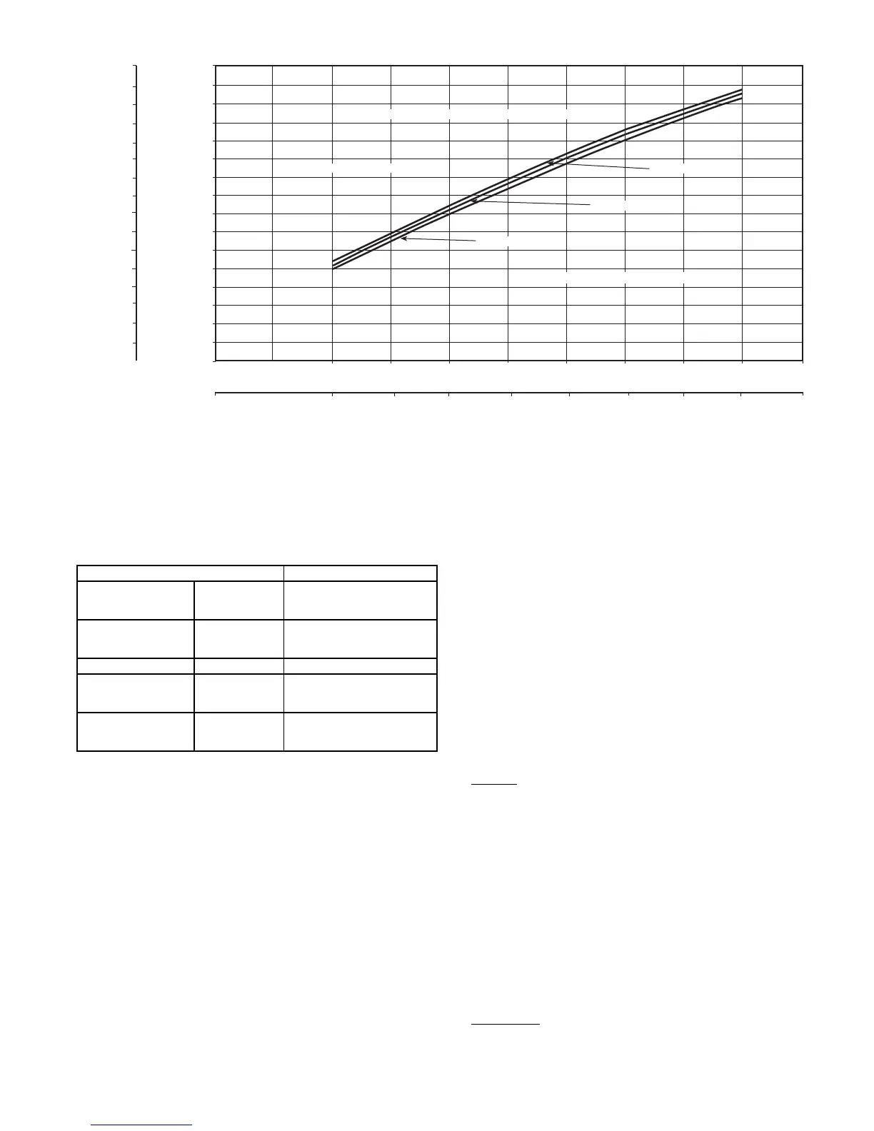
556E240
566E180
566E150
BOTH OUTDOOR FANS MUST BE OPERATING
REDUCE CHARGE IF BELOW CURVE
ADD CHARGE IF ABOVE CURVE
LIQUID TEMPERATURE AT LIQUID VALVE (C)
LIQUID TEMPERATURE AT LIQUID VALVE (F)
160.00
150.00
140.00
130.00
120.00
110.00
100.00
90.00
80.00
70.00
71
66
60
64
49
43
38
32
27
21
16
10
4
-1
-7
-12
60.00
50.00
40.00
30.00
20.00
10.00
0.00
100
690
150
200
1030
1379
1720
250 300
2069
350 400
2410
2758
3100
450 500
3448
LIQUID PRESSURE AT LIQUID VALVE (psig)
LIQUID PRESSURE AT LIQUID VALVE (kPa)
Fig. 18 — 566E150-240 Charging Chart
 Loading...


