—22—
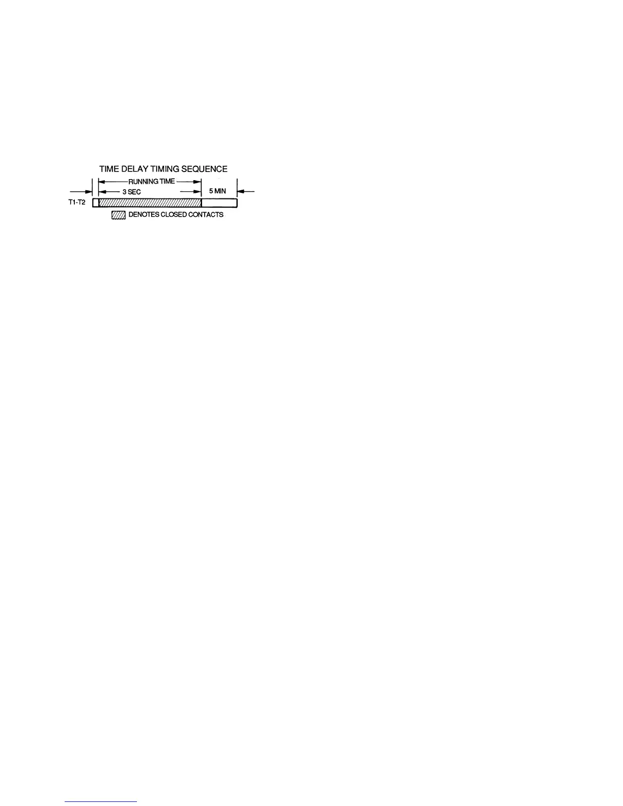
III. TIME GUARD II CIRCUIT (566D ONLY)
Circuit prevents short-cycling by providing a delay of
approximately 5 minutes before restarting compressor after
shutdown from safety device action.
On start-up, the Time Guard II timer causes a delay of
approximately 3 seconds after thermostat closes.
On compressor shutdown, the timer recycles for approxi-
mately 5 minutes. During this time, the compressor cannot
restart.
Refer to Fig. 21 and to label diagram on unit.
IV. CRANKCASE HEATER
The heater prevents refrigerant migration and compressor
oil dilution during shutdown whenever compressor is not
operating. It is wired to cycle with the compressor; the
heater is off when compressor is running, and on when com-
pressor is off.
Both compressor service valves must be closed whenever the
crankcase heater is deenergized for more than 6 hours.
The crankcase heater is operable as long as the control cir-
cuit is energized.
V. COMPRESSOR PROTECTION
A. Circuit Breaker (566D Only)
Calibrated trip manual reset, ambient compensated, mag-
netic breaker protects against motor overload and locked
rotor conditions.
B. Compressor Overtemperature Protection (IP)
A thermostat installed on compressor motor winding reacts
to excessively high winding temperatures and shuts off the
compressor.
C. Time Guard II Control (566D Only)
Control prevents compressor from short cycling. See Operat-
ing Sequence.
D. Crankcase Heater
Heater minimizes absorption of liquid refrigerant by oil in
crankcase during brief or extended shutdown periods. The
control circuit is maintained if compressor fan motor circuit
breakers are turned off. The main disconnect must be on to
energize crankcase heater.
IMPORTANT: Never open any switch or disconnect that ener-
gizes the crankcase heater unless unit is being serviced or is
to be shut down for a prolonged period. After a prolonged
shutdown on a service job, energize the crankcase heater for
24 hours before starting the compressor.
E. Advanced Scroll Temperature Protection (ASTP)
See Advanced Scroll Temperature Protection (ASTP) on
page 16.
VI. LOW-PRESSURE SWITCHES
The 569D, 569F, 566E, 576C low-pressure switches are
mounted on the suction line. The 566D low-pressure
switches are mounted on the compressor. Switches are all
fixed, non-adjustable type.
VII. HIGH-PRESSURE SWITCHES
The 569D, 576C and 569F high-pressure switches are
mounted on the liquid line. The 566E150-240 high-pressure
switches are mounted on the discharge line. The 566D
high-pressure switches are mounted on the compressor. The
switches are all fixed, non-adjustable type.
A. To Check
Slowly close liquid shutoff valve and allow compressor to
pump down. Do not allow compressor pumpdown below
2 psig. Compressor should shut down when suction pressure
drops to cutout pressure in Tables 1A-1C, and should restart
when pressure builds up to cut-in pressure shown.
VIII. DISCHARGE GAS THERMOSTAT (569D090 ONLY)
A sensor on the discharge line will stop the compressor if an
abnormally high discharge temperature is detected. If the
unit shuts down on a high discharge temperature fault,
restart the unit by cycling the thermostat or the power
disconnect switch.
IX. OUTDOOR FANS
Each fan is supported by a formed-wire mount bolted to the
fan deck and covered with a wire guard. Fan motors have per-
manently lubricated bearings.
NOTE: On 566D units, the exposed end of the motor shaft is
covered with a rubber boot. In case a fan motor must be
repaired or replaced, be sure the rubber boot is put back on
when the fan is reinstalled and be sure the fan guard is in
place before starting the unit. Figure 22 shows the proper
position of the mounted fan.
X. LUBRICATION
Fan motors have sealed bearings. No provisions are made for
lubrication.
Compressor has its own oil supply. Loss of oil due to a leak in
the system should be the only reason for adding oil after the
system has been in operation.
XI. COIL CLEANING AND MAINTENANCE
This section discusses the cleaning and the maintenance of
standard coils and E-Coated coils. Routine cleaning of coil
surfaces is essential to minimize contamination build-up and
remove harmful residue. Inspect coils monthly and clean as
required.
A. Cleaning Standard Coils
Standard coils can be cleaned with a vacuum cleaner,
washed out with low velocity water, blown out with low-pres-
sure compressed air, or brushed (do not use wire brush). Fan
motors are drip-proof but not waterproof. Do NOT use acid
cleaners.
Clean outdoor coil annually or as required by location or out-
door air conditions. Inspect coil monthly, and clean as
required. Fins are not continuous through coil sections; dirt
and debris may pass through first section, become trapped
between second and third rows of fins and restrict outdoor
airflow. Use a flashlight to determine if dirt or debris has
collected between coil sections. Clean coil as follows:
1. Turn off unit power.
2. Remove screws holding rear corner posts and top
cover in place. Pivot top cover up 12 to 18 in. and
support with a rigid support. See Fig. 23.
3. Remove clips securing tube sheets together at the
return bend end of the coil. Carefully spread the ends
of the coil rows apart by moving the outer sections.
See Fig. 24.
Fig. 21 — Timer Sequence Chart