—9—
II. RIG AND MOUNT THE UNIT
A. Rigging
These units are designed for overhead rigging. Refer to rig-
ging label for preferred rigging method. Spreader bars are
not required if top crating is left on unit. All panels must be
in place when rigging. As further protection for coil faces,
plywood sheets may be placed against sides of unit, behind
cables. Run cables to a central suspension point so that angle
from the horizontal is not less than 45 degrees. Raise and set
unit down carefully.
If it is necessary to roll the unit into position, mount the unit
on longitudinal rails, using a minimum of 3 rollers. Apply
force to the rails, not the unit. If the unit is to be skidded into
position, place it on a large pad and drag it by the pad. Do
not apply any force to the unit.
Raise from above to lift unit from the rails or pad when unit
is in final position.
After unit in position, remove all shipping materials and top
crating.
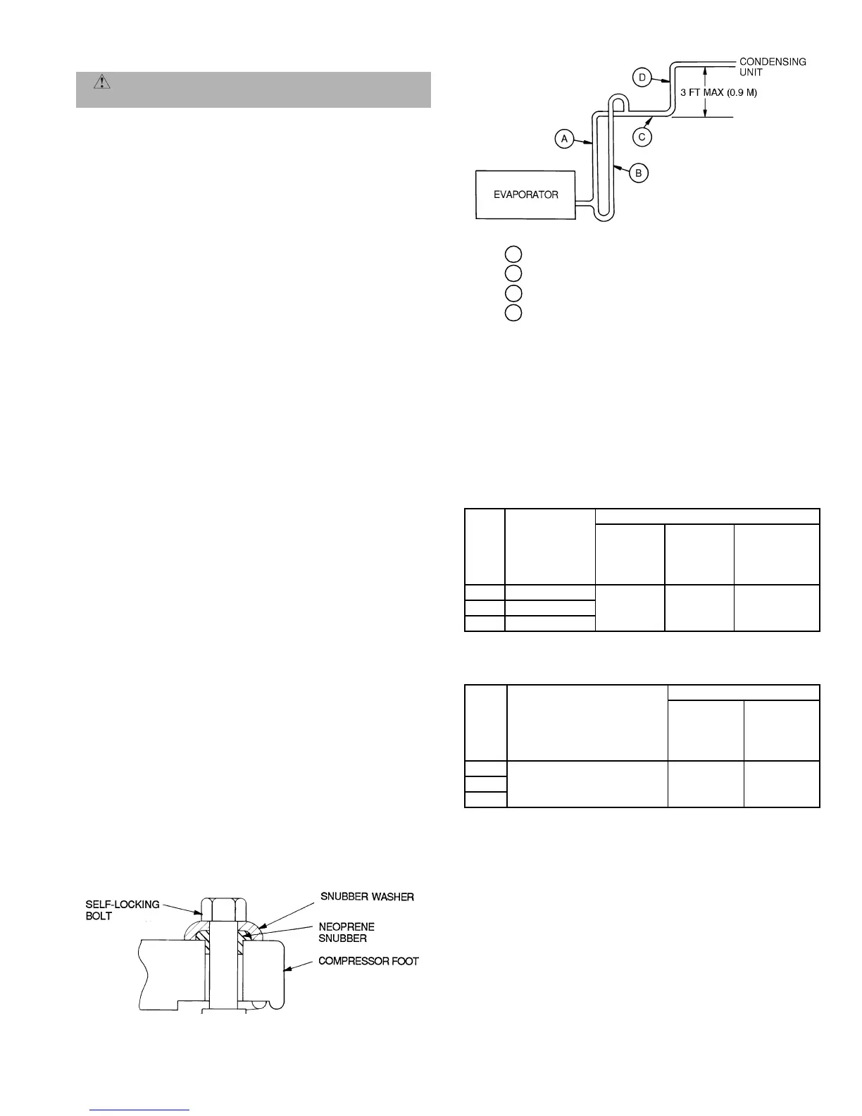
B. Compressor Mounting
As shipped, the compressor is held tightly in place by self-
locking bolts. Before starting unit, loosen self-locking
bolts until the snubber washer can be moved side-
ways with finger pressure. Do not remove shipping
bolts. See Fig. 5.
III. COMPLETE REFRIGERANT PIPING CONNECTIONS
IMPORTANT: DO NOT bury refrigerant piping underground.
IMPORTANT: A refrigerant receiver is not provided with the
unit. Do not install a receiver.
A. Size Refrigerant Lines
Consider the length of piping required between outdoor unit
and indoor unit (evaporator), the amount of liquid lift, and
compressor oil return. See Tables 2A-4. Refer to indoor unit
installation instructions for additional information.
IMPORTANT: Use the piping data in Tables 2A-4 as a
general guide only. For 569D, 576C, 569F applications with
liquid lift greater than 20 ft, use
5
/
8
-in. liquid line. Maximum
lift is 60 ft.
Condensing units with multiple-step unloading may require
double suction risers to assure proper oil return at minimum
load operating condition. See Tables 3A-4 and Fig. 6. Reduc-
tion of evaporator coil surface should be analyzed to provide
sufficient refrigerant velocity to return oil to the compressor.
Liquid line solenoid valves may be used in certain situations
to accomplish this. Hot gas bypass, if used, should be intro-
duced before the evaporator.
Note that refrigerant suction piping should be insulated.
Table2A—LiquidLineData—
566D150-240 Units
Table2B—LiquidLineData—
566E150-240 Units
*Inlet and outlet.
NOTE: Data shown is for units operating at 45 F (7.2 C) saturated suc-
tion and 95 F (35 C) entering air.
CAUTION: Be sure unit panels are securely in
place prior to rigging.
UNIT
566D
MAXIMUM
ALLOWABLE
LIQUID LIFT
ft (m)
LIQUID LINE
Maximum
Allowable
Pressure
Drop
psig (kPa)
Maximum
Allowable
Temp.
Loss
F(C)
Filter Drier
and
Sight Glass
Flare Conn.*
in.
150 67 (20.4)
7 (48.3) 2 (1.1)
5
/
8
180 82 (25.0)
240 87 (26.5)
UNIT
566E
MAXIMUM
ALLOWABLE
LIQUID LIFT
ft (m)
LIQUID LINE
Maximum
Allowable
Pressure
Drop
psig (kPa)
Maximum
Allowable
Temp.
Loss
F(C)
150
60 (18) 7 (48) 2 (1)180
240
LEGEND
A — Suction Riser
Without
Tr ap
B — Suction Riser
With
Trap
C — Suction Line to Condensing Unit
D — Short Vertical Riser into Condensing Unit:
566D150,180 — 1
3
/
8
in. OD
566D240 — 1
5
/
8
in. OD
Fig. 6 — Suction Line Piping
Fig. 5 — Compressor Mounting