—11—
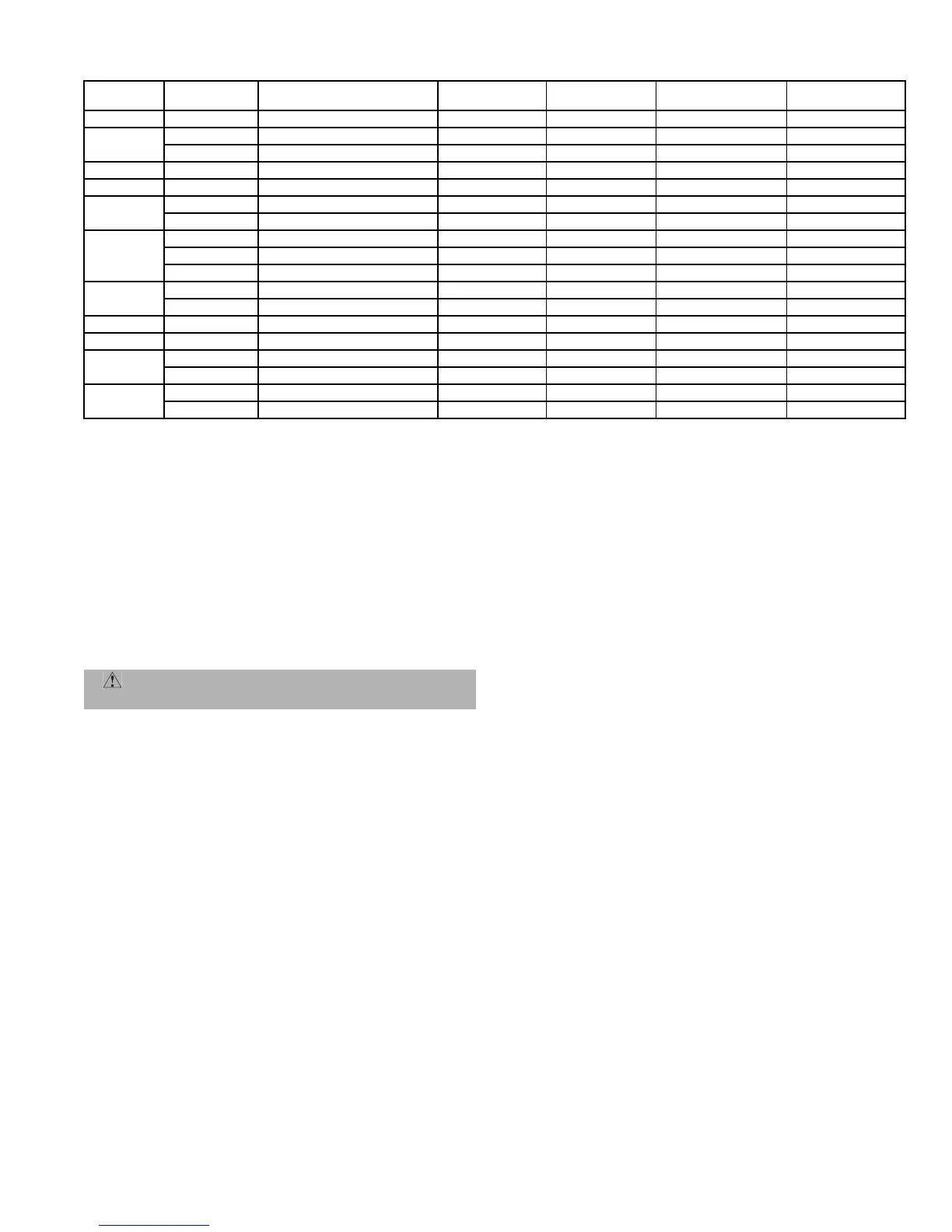
Table 5 — Refrigerant Specialities Part Numbers
*Bushings required.
D. Install Liquid Line Solenoid Valve (Optional) — Capacity
Control
If 2-step cooling is desired, place a solenoid valve in the loca-
tion shown in Fig. 7.
E. Make Piping Connections
Do not remove runaround loop from suction and liquid line
stubs in the compressor compartment until piping connec-
tions are ready to be made. Pass nitrogen or other inert gas
through piping while brazing to prevent formation of copper
oxide.
1. Open service valves:
a. Discharge service valve on compressor.
b. Suction service valve on compressor.
c. Liquid line valve.
2. Remove
1
/
4
-in. flare cap from liquid valve Schrader
port.
3. Attach refrigerant recovery device and recover hold-
ing charge.
4. Remove runaround loop.
5. Install a field-supplied liquid moisture indicator in
the piping immediately leaving outdoor unit.
6. If necessary, install field-supplied thermostatic
expansion valve(s) (TXVs) in air handler.
If 2 TXVs are installed and two-step cooling is desired,
install field-supplied capacity control liquid line solenoid
valve ahead of the upper TXV (see Fig. 7).
F. Provide Safety Relief
A fusible plug is located on the compressor crankcase or in
the liquid line (Fig. 8). Do not cap this plug. If local code
requires additional safety devices, install them as directed.
IV. INSTALL ACCESSORIES
Field install accessories such as low-ambient control before
proceeding with wiring. Refer to the instructions shipped
with the accessory.
V. COMPLETE ELECTRICAL CONNECTIONS
A. Power Wiring
Unit is factory wired for voltage shown on nameplate. Pro-
vide adequate fused disconnect switch within sight from unit
and readily accessible from unit, but out of the reach of chil-
dren. Lock switch open (off) to prevent power from being
turned on while unit is being serviced. Disconnect switch,
fuses, and field wiring must comply with national and local
code requirements. See Tables 6A-6C.
Route power wires through opening in unit end panel to con-
nection in unit control box as shown on unit label diagram
and in Fig. 9. Unit must be grounded.
Affix crankcase heater warning sticker to unit disconnect
switch.
B. Control Circuit Wiring
Control voltage is 24 v. See Fig. 10 and unit label diagram for
field-supplied wiring details. Route control wires through
opening in unit end panel to connection in unit control box.
C. Control Transformer Wiring (569D, 576C, 569F Units
Only)
On multivoltage units, check the transformer primary wir-
ing connections. See Fig. 11 or refer to unit label diagram.
If unit will be operating at 208-3-60 power, remove black
wire (BLK) from the transformer primary connection
labelled “230” and move it to the connection labelled “208”.
See Fig. 11.
UNIT
LIQUID LINE
SIZE (in.)
LIQUID LINE
SOLENOID VALVE (LLSV)
LLSV
COIL
SIGHT
GLASS
FILTER
DRIER
SUCTION LINE
ACCUMULATOR
569D072
3
/
8
200RB5T3M AMG/24V AMI-1TT3 P502-8304S* S-7063S*
569D090
3
/
8
200RB5T3M AMG/24V AMI-1TT3 P502-8304S* S-7063S*
1
/
2
200RB5T4M AMG/24V AMI-1TT4 P502-8304S S-7063S*
569D120
1
/
2
200RB6T4M AMG/24V AMI-1TT4 P502-8307S* S-7063
576C120
1
/
2
200RB6T4M AMG/24V AMI-1TT4 P502-8307S* S-7063
566D150
1
/
2
200RB7T4M AMG/24V AMI-1TT4 P502-8757S* S-7063
5
/
8
200RA8T5M AMG/24V AMI-1TT5 P502-8757S* S-7063
566D180
1
/
2
200RB7T4M AMG/24V AMI-1TT4 P502-8757S* S-7721
5
/
8
240RA8T5M AMG/24V AMI-1TT5 P502-8757S* S-7721
7
/
8
200RA8T7M AMG/24V AMI-1TT7 P502-8757S S-7721
566D240
5
/
8
200RA9T5M AMG/24V AMI-1TT5 P502-8757S* S-7721
7
/
8
200RA9T7M AMG/24V AMI-1TT7 P502-8757S S-7721
569F120
3
/
8
200RB5T3M Qty 2 AMG/24VQty 2 AMI-1TT3 Qty 2 P502-8304S* Qty 2 S-7061 Qty 2
566E150
1
/
2
200RB5T4M Qty 2 AMG/24VQty 2 AMI-1TT4 Qty 2 P502-8304S Qty 2 S-7063S* Qty 2
566E180
1
/
2
200RB5T4M Qty 2 AMG/24VQty 2 AMI-1TT4 Qty 2 P502-8304S Qty 2 S-7063S Qty 2
5
/
8
200RB5T5M Qty 2 AMG/24VQty 2 AMI-1TT5 Qty 2 P502-8305S Qty 2 S-7063S Qty 2
566E240
1
/
2
200RB6T4M Qty 2 AMG/24VQty 2 AMI-1TT5 Qty 2 P502-8307S* S-7063S Qty 2
5
/
8
200RB6T5M Qty 2 AMG/24VQty 2 AMI-1TT5 Qty 2 P502-8307S* S-7063S Qty 2
WARNING: Recover holding charge prior to
removal of runaround piping loop.
 Loading...