—12—
LEGEND
NOTES:
1. Combination LLSV plus IFC va should not exceed 30 va.
2. Do not exceed 5 va (24 vac) per coil.
3. If va values shown in Notes 1 and 2 must be exceeded, use
accessory relay transformer package 38AE900001 (60 Hz).
C—Compressor Contactor
HD — Heating Device
IFC — Indoor-Fan Contactor
LLSV1 — Liquid Line Solenoid Valve 1 — Refrigerant Migration
Control
LLSV2 — Liquid Line Solenoid Valve 2 — Capacity Control
R—Relay
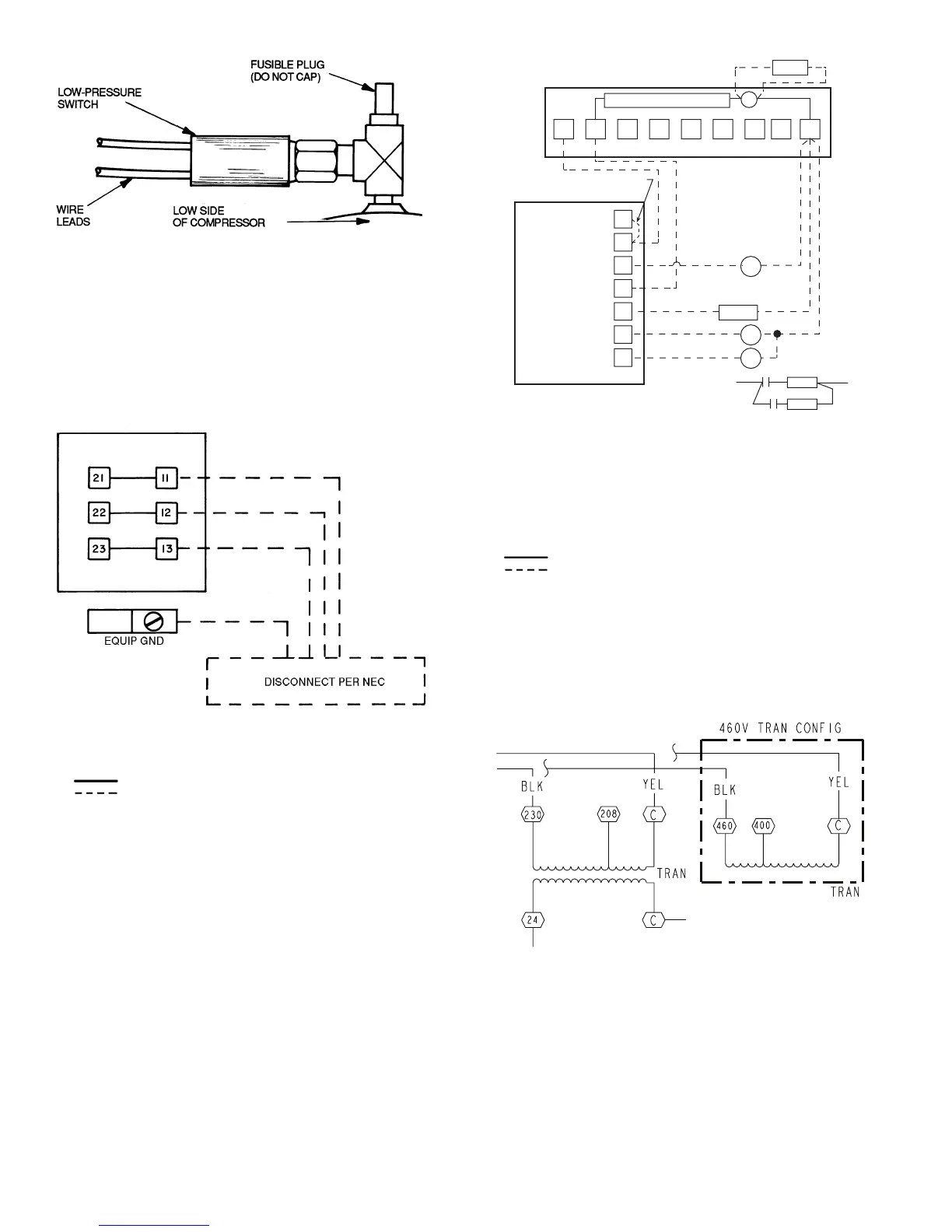
Factory Wiring
Field Wiring
Fig. 11 — Control Transformer Wiring
(569D, 576C, 569F Unit Shown)
Fig. 10 — Typical Remote Thermostat Wiring
(566D Unit Shown)
LEGEND
NOTE: Terminal block (TB1) is used for 566E150-240 and 566D150-
240 units. Pigtails are provided on 569D, 576C, 569F units.
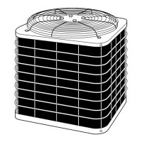
Fig. 9 — Main Power Supply Wiring
(566D Unit Shown)
EQUIP GND — Equipment Ground
NEC — National Electrical Code
Factory Wiring
Field Wiring
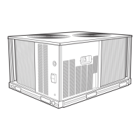
NOTES:
1. 566D240 has a fusible plug in the liquid line.
2. 569D120, 576C120 and 569F120 units have a fusible joint in the
liquid line.
Fig. 8 — Location of Fusible Plug (566D)
1
2
3
4
5
6
7
8
9
C
LLSV1
TIME GUARD CIRCUIT
TERMINAL BOARD TB2
IN CONTROL BOX
ACCESSORY
THERMOSTAT
JUMPER
G
RC
RH
Y1
Y2
W1
W2
IFC
NOTE 1
LLSV2
R1
R2
NOTE 2
R1
L2
L1
R2
HD1
HD2
 Loading...