1. Operate unit a minimum of 10 minutes before checking
charge.
2. Measure liquid service valve pressure by attaching an
accurate gage to service port.
3. Measure liquid line temperature by attaching an accurate
thermistor type or electronic thermometer to liquid line near
outdoor coil.
4. Refer to Table 8 for required subcooling temperature.
5. Refer to Table 7. Find the point where required subcooling
temperature intersects measured liquid service valve pres-
sure.
6. To obtain required subcooling temperature at a specific
liquid line pressure, add refrigerant if liquid line tempera-
ture is higher than indicated or reclaim refrigerant if
temperature is lower. Allow a tolerance of ± 3°F.
XII. SYSTEM FUNCTIONS AND SEQUENCE OF OPERA-
TION
The outdoor unit control system has special functions. The
following is an overview of the two-speed control functions:
A. COOLING OPERATION
This product utilizes a 2-stage cooling indoor thermostat. With a
call for first stage cooling (Yl), the outdoor fan and low capacity
compressor are energized. If low capacity cannot satisfy cooling
demand, high capacity is energized (Yl and Y2 or Y2 only) by the
second stage of indoor thermostat. After second stage is satisfied,
the unit returns to low-speed operation until first stage is satisfied
or until second stage is required again. When both one stage and
two stage cooling are satisfied, the compressor will shut off.
NOTE: When two-speed unit is operating at low speed, system
vapor (suction) pressure will be higher than a standard single-
speed system or high-speed operation. This normal operation is
due to the reduced capacity operating with typically larger indoor
and outdoor coils.
NOTE: Outdoor fan motor will continue to operate for one
minute after compressor shuts off, when outdoor ambient is greater
than or equal to 100°F.
B. STATUS FUNCTION LIGHTS
A system control STATUS function light is located on the outdoor
unit control board (see Fig. 10). The STATUS light provides
signals for several system operations. See Table 9 for codes and
definitions. Table 9 also provides the order of signal importance.
NOTE: Only one code will be displayed on the outdoor unit
control board (the most recent, with the highest priority).
C. FACTORY DEFAULTS
Factory defaults have been provided in the event of failure of
outdoor air thermistor, coil thermistor, and/or furnace interface
jumper.
D. ONE MINUTE SPEED CHANGE TIME DELAY
When compressor changes speeds from high to low or low to high,
there is a 1 minute time delay before compressor restarts. The
outdoor fan motor remains running.
E. COMPRESSOR OPERATION
When the compressor operates in high capacity operation, the
motor rotates clockwise. Both the lower and upper pistons are
eccentric with the rotating crankshaft and both compress refriger-
ant. When the compressor operates in low capacity the motor
reverses direction (rotates counterclockwise). The lower piston
becomes idle since it is in line with the compressor crankshaft and
the upper piston which is eccentric with the rotating crankshaft
compresses refrigerant. The start and run windings are reversed.
F. CRANKCASE HEATER OPERATION
The two-speed control energizes crankcase heater during unit off
cycle.
G. OUTDOOR FAN MOTOR OPERATION
The outdoor unit control energizes outdoor fan any time compres-
sor is operating. The outdoor fan remains energized during the 1
minute speed change time delay and if a pressure switch or
compressor overload should trip. Outdoor fan motor will continue
to operate for one minute after the compressor shuts off when the
outdoor ambient is greater than or equal to 100°F.
H. COMPRESSOR VOLTAGE FAILURE (6 FLASHES)
The control senses the voltage of the compressor run winding. If
compressor voltage (Vc) is out of range (less than 90v or greater
than 600v), control shuts compressor off for 15 minutes with
outdoor fan running. After 15 minutes (provided there is a call for
Y1 or Y2), control attempts to start compressor. During this time,
a code of 6 flashes appears at control board. If Vc trip occurs 3
consecutive times during a Y1 request, then low capacity operation
is locked out and control responds to Y2 requests until a reset
occurs. If 3 consecutive trips occur in a combination of Yl and Y2
or all Y2 requests, then both low and high capacity operation will
be locked out. The compressor voltage failure (6 flashes) can be
caused by:
• compressor internal overload trip
• no 240 volt power supply to outdoor unit
• failed compressor contactor(s)
• failure of start relay to pick up properly.
I. PRESSURE SWITCH PROTECTION
The outdoor unit is equipped with high- and low-pressure
switches. If the control senses the opening of a high or low
pressure switch, it will respond as follows:
1. De-energize the compressor low or high speed contactor,
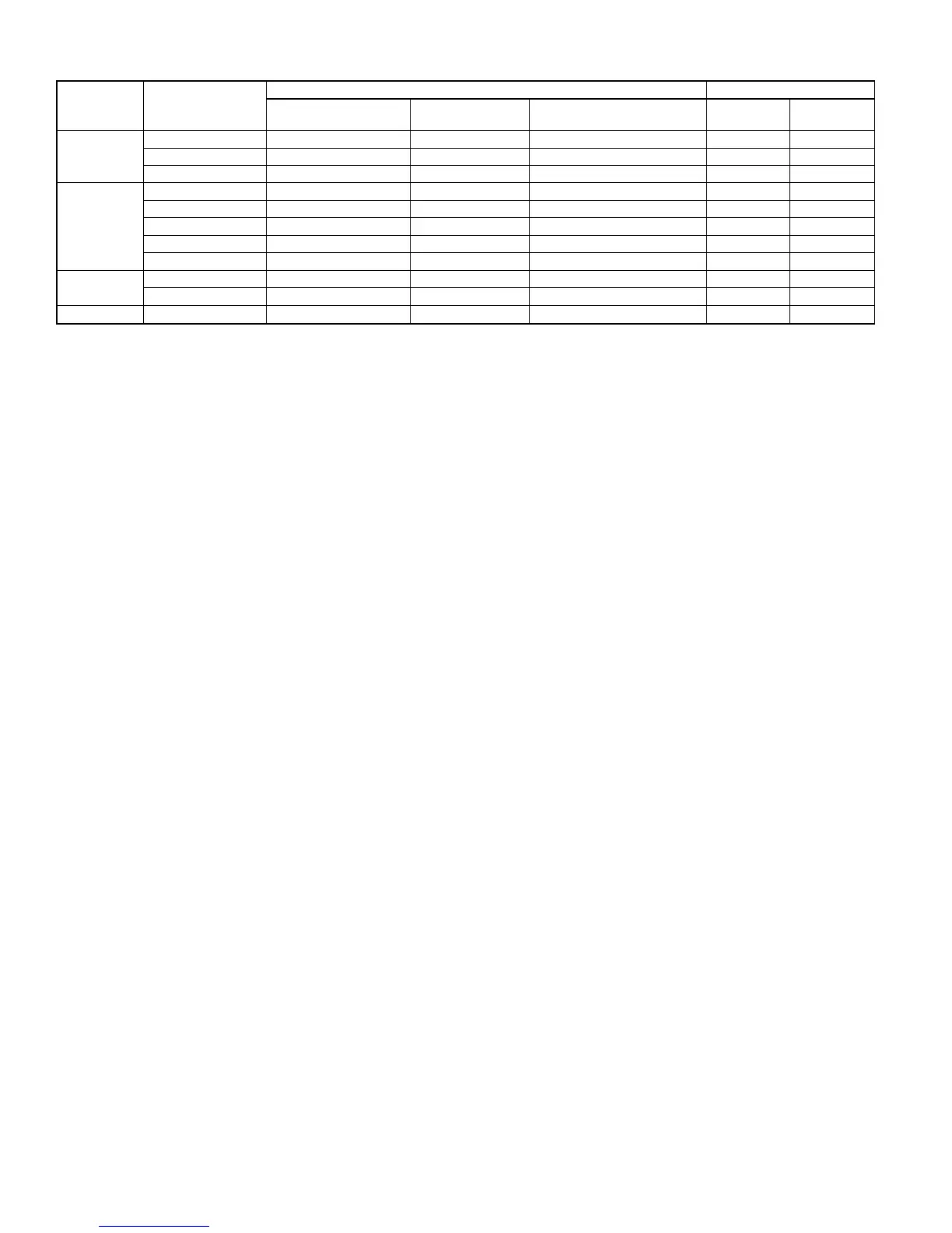
TABLE 6—AIRFLOW SELECTION FOR FK4C OR FV4A FAN COILS (CFM)
598B
UNIT
SIZE
FK4C/FV4A
EASY SELECT CONTROL BOARD CFM*
SYSTEM TYPE
(Orange Wire)
A/C TYPE
(Blue Wire)
AC/HP CFM ADJUST
(Black Wire)
High Low
024
001 AC 024 NOM 735 441
002 AC 024 NOM 735 441
003 AC 024 NOM 735 441
036
001 AC 036 NOM 1100 662
002 AC 036 NOM 1100 662
003 AC 036 NOM 1100 662
005 AC 036 NOM 1100 662
006 AC 036 NOM 1100 662
048
005 AC 048 NOM 1470 882
006 AC 048 NOM 1470 882
060 006 AC 060 NOM 1835 1103
* Airflow CFMs are given with AC/HP CFM ADJUST jumper set at NOM. Airflow can be adjusted 15 percent or −10 percent by selecting HI or LO, respectively.
—8—
 Loading...