15
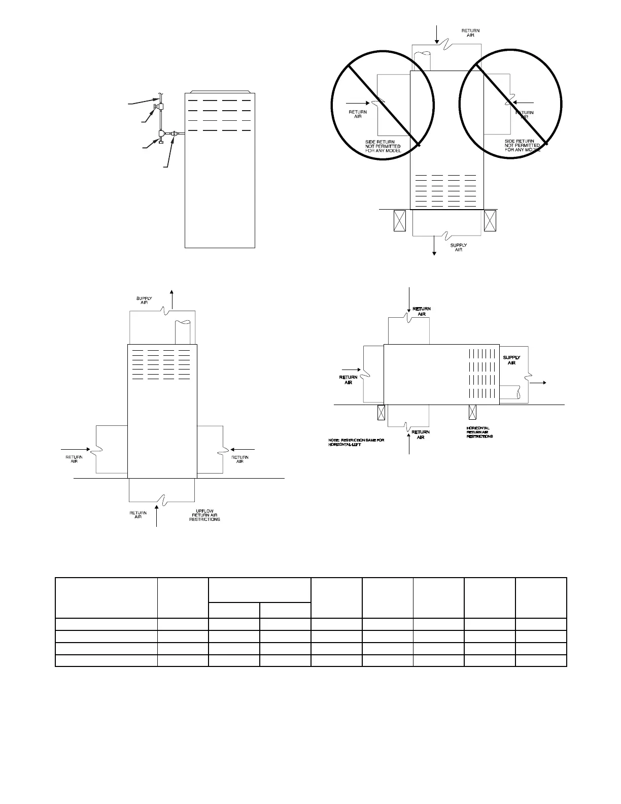
shutoff valve before and during supply pipe pressure test. After
all connections have been made, purge lines and check for
leakage at furnace prior to operating furnace.
The gas supply pressure shall be within the maximum and
minimum inlet supply pressures marked on the rating plate with
the furnace burners ON and OFF.
UNION
SEDIMENT
TRAP
MANUAL
SHUTOFF
VALVE
(REQUIRED)
GAS
SUPPLY
A02035
Fig. 18 -- Typical Gas Pipe Arrangement
A190364
Fig. 19 -- Upflow Return Air Configura tions and Restrictions
A190365
Fig. 20 -- Downflow Return Air Configurations and Restric-
tions
A190366
Fig. 21 -- Horizontal Return Air Configurations and Restric-
tions
Table 7 – Electrical Data
Unit Size
Volts-
Hertz -
Phase
Operating Voltage*
Range
Maximum
Unit Amps
Unit
Ampacity#
Minimum
Wire Size
AWG
Maximum
Wire
Length‡ ft
(m)
Maximum
Fuse or
CKT BKR†
Amps
Maximum Minimum
36040E17 115-60-1 127 104 10.6 13.9 14 26 (8) 15
48060E17 115-60-1 127 104 10.6 13.9 14 26 (8) 15
60080E21 115-60-1 127 104 13.3 17.3 12 33 (10) 20
60100E21 115-60-1 127 104 13.3 17.3 12 33 (10) 20
* Permissible limits of the voltage range at which the unit operates satisfactorily .
# Unit ampacity = 125 percent of largest operating component’s full load amps plus 100 percent of all other potential operating components’ (EAC, humidifier,
etc.) full load amps.
{ Time---delay type is recommended.
} Length shown is as measured one way along wire path between unit and service panel for maximum 2 percent voltage drop.