14
1. Gas supply connections MUST be performed by a
licensed plumber or gas fitter.
2. When flexible connectors are used, the maximum length
shall not exceed 36 inches (915 mm).
3. When lever handle type manual equipment shutoff valves
are used, they shall be T-- handle valves.
4. The use of copper tubing for gas piping is NOT approved
by the state of Massachusetts.
Refer to Table 6 for recommended gas pipe sizing. Risers must be
used to connect to furnace and to meter. Support all gas piping
with appropriate straps, hangers, etc. Use a minimum of 1 hanger
every 6 ft. (2 M). Joint compound (pipe dope) should be applied
sparingly and only to male threads of joints. Pipe dope must be
resistant to the action of propane gas.
An accessible manual equipment shutoff valve MUST be
installed external to furnace casing and within 6 ft. (2 M) of
furnace. A 1/8--in. (3 mm) NPT plugged tapping, accessible for
test gauge connection, MUST be installed immediately upstream
of gas supply connection to furnace and downstream of manual
equipment shutoff valve.
NOTE: The furnace gas control valve inlet pressure tap
connection is suitable to use as test gauge connection providing
test pressure DOES NOT exceed maximum 0.5 psig (14--In.
W.C.) stated on gas control v alve. (See Fig. 32)
Install a sediment trap in riser leading to furnace as shown in Fig.
18. Connect a capped nipple into lower end of tee. Capped nipple
should extend below level of furnace gas controls. Place a ground
joint union between furnace gas control valve and exterior
manual equipment gas shutoff valve. A 1/8 -- in. (3 mm) NPT
plugged tapping, accessible for test gauge connection, MUST be
installed immediately upstream of gas supply connection to
furnace and downstream of manual equipment shutoff valve.
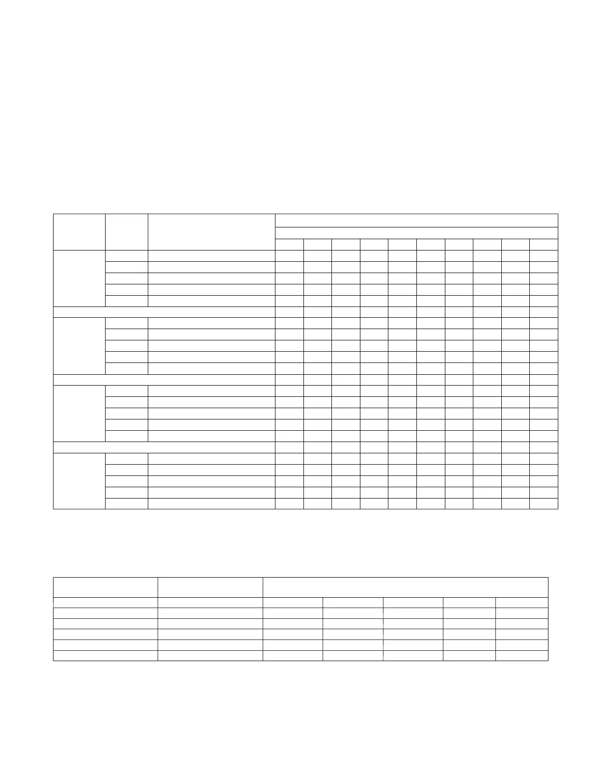
Table 5 – Air Delivery -- CFM (With Filter)
Furnace
Wire Lead
Color
2
Function
Test
irflow Delivery @ Various External Static Pressures
External Static Pressure (IN. W.C.)
0.1 0.2 0.3 0.4 0.5 0.6 0.7 0.8 0.9 1.0
036040E17
Gray Cooling. Do not use for heating. 1535 1495 1455 1415 1370 1320 1280 1235 1190 1145
Yellow
lt Cooling or alt Heating 1100 1055 1005 955 905 855 800 740 680 625
Orange Heating or alt cooling 695 645 585 510 450 390 325 270 215 155
Blue
lt Cooling or alt Heating 935 885 830 775 720 655 595 540 490 430
Red
lt Cooling or alt Heating 570 455 380 310 250 180 110 --- --- ---
0.1 0.2 0.3 0.4 0.5 0.6 0.7 0.8 0.9 1.0
048060E17
Gray Cooling. Do not use for heating. 1720 1680 1635 1585 1545 1505 1455 1405 1355 1305
Yellow
lt Cooling or alt Heating 1470 1425 1385 1335 1290 1245 1200 1160 1110 1060
Orange
lt Cooling or alt Heating 1305 1255 1215 1160 1115 1070 1025 975 925 870
Blue Heating or alt cooling 1040 940 890 835 790 740 675 620 565 525
Red
lt Cooling or alt Heating 1135 1090 1035 985 940 895 845 790 730 675
0.1 0.2 0.3 0.4 0.5 0.6 0.7 0.8 0.9 1.0
060080E21
Gray Cooling. Do not use for heating. 2185 2135 2085 2035 1990 1935 1880 1825 1770 1715
Yellow
lt Cooling or alt Heating 1885 1830 1780 1730 1675 1625 1575 1520 1470 1420
Orange
lt Cooling or alt Heating 1565 1500 1440 1385 1330 1275 1220 1170 1115 1055
Blue Heating or alt cooling 1365 1295 1230 1165 1100 1045 985 925 845 780
Red
lt Heating or alt cooling 1205 1045 965 895 815 745 650 595 540 480
0.1 0.2 0.3 0.4 0.5 0.6 0.7 0.8 0.9 1.0
060100E21
Gray Cooling. Do not use for heating. 2230 2180 2120 2060 2005 1945 1880 1815 1755 1700
Blue Heating or alt cooling 1945 1885 1830 1770 1715 1650 1585 1525 1465 1405
Yellow
lt Cooling or alt Heating 1835 1775 1720 1655 1595 1530 1470 1410 1350 1285
Orange
lt cooling or alt Heating 1535 1470 1395 1325 1265 1205 1140 1080 1015 955
Red
lt cooling. Do not use for heating 1095 1060 1020 985 950 915 880 845 805 770
1. A filter is required for each return---air inlet. Airflow performance included 3/4---in. (19 mm) washable filter media such as contained in factory --- a u t h o r i z e d
accessory filter rack. To determine airflow performance without this filter, assume an additional 0.1---in. W.C. available external static pressure.
2. Adjust the blower speed tabs as necessary for the proper air temperature rise for each installation.
--- --- Indicates unstable operating conditions
Table 6 – Maximum Capacity of Pipe*
NOMINAL IRON
PIPE
INTERNAL
DIAMETER
LENGTH OF PIPE --- FT. (M)
SIZE IN. (mm) In. (mm) 10 20 30 40 50
1/2 (13) 0.622 (16) 175 (53) 120 (37) 97 (30) 82 (25) 73 (22)
3/4 (19) 0.824 (21) 360 (110) 250 (76) 200 (61) 170 (52) 151 (46)
1 (25) 1.049 (27) 680 (207) 465 (142) 375 (114) 320 (98) 285 (87)
1 --- 1
4 (32) 1.380 (35) 1400 (427) 950 (290) 770 (235) 660 (201) 580 (177)
1 --- 1
2 (38) 1.610 (41) 2100 (640) 1460 (445) 1180 (360) 990 (301) 900 (274)
* Cubic ft. of natural gas per hr for gas pressures of 0.5 psig (14 ---In. W.C.) or less and a pressure drop of 0.5 ---In. W.C. (based on a 0.60 specific gravity
gas). Ref: Ch a pter 6 curren t edition of ANSI Z223/NFPA 54.
Piping should be pressure and leak tested in accordance with
NFGC in the United States, local, and national plumbing and gas
codes before the furnace has been connected. After all
connections have been made, purge lines and check for leakage at
furnace prior to operating furnace.
If pressure exceeds 0.5 psig (14--In. W.C.), gas supply pipe must
be disconnected from furnace and capped before and during
supply pipe pressure test. If test pressure is equal to or less than
0.5 psig (14 -- In. W.C.), turn off electric shutoff switch located on
furnace gas control valve and accessible manual equipment