23
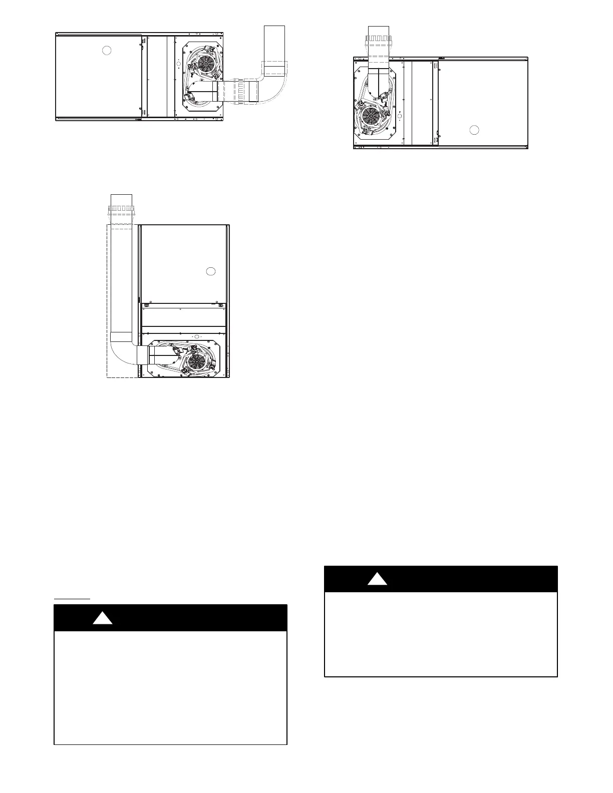
SEE NOTES: 1,2,4,7,8,9 on the page
following these figures
A03214
Fig. 29 -- Horizontal Right Application-- Vent Elbow Right
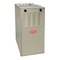
SEE NOTES: 1,2,4,5,6,7,8,9
on the page following these figures
A03207
Fig. 30 -- Downflow Application--Vent Elbow Left then Up
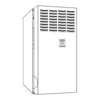
SEE NOTES: 1,2,4,5,7,8,9 on the page
following these figures
A03215
Fig. 31 -- Horizontal Left Application --Vent Elbow Up
See NOTES following images.
VENTING NOTES FOR FIGURES 26 -- 31
1. For common ven t, vent co nnector sizing and vent material: United States----use the NFGC.
2. Immediately increase to 5--inch (127 mm) or 6-- inch (152 mm) vent connector outside furnace casing when 5-- inch (127 mm) vent connector is required, refer to Note 1
above.
3. Side outlet vent for upflow and downflow installations must u se Type B vent immediately after exiting the furnace, except when factory--authorized, Downflo w Vent
Guard Kit, is used in the downflow position. See Product Data Sheet for accessory listing.
4. Type-- B vent where required, refer to Note 1 above.
5. Four--in ch single--wall (26 g a. min.) vent must be used inside fur nace casing and when th e Downflo w Vent Guard Kit is used external to the furnace. SeeProductData
Sheet for accessory listing.
6. Factory--authorized accessory Downflow Vent Gu ard Kit required in downflow installations with lower vent conf iguration. See Product Data Sheet for accessory listing.
7. Secure v e nt connector to fur nace elbow with (2 ) corr osion -- resistant sheet metal screws, spaced app roximately 180_ apart.
8. Secure all other single wall vent connector joints with (3) corrosion resistant screws spaced approxim ately 120_ apart.
9. Secure Type--B vent connectors per vent connector manufacturer’s recommendations.
START--UP, ADJUSTMENT, AND SAFETY
CHECK
General
FIRE HAZARD
Failure to follow this warning could result in personal
injury, death and/or property damage.
This furnace is equipped with manual reset limit switches in
the gas control area. The switches open and shut off power
to the gas valve if a flame rollout or overheating condition
occurs in the gas control area. DO NOT bypass the
switches. Correct inadequate combustion air supply
problem before resetting the switches.
!
WARNING
CUT HAZARD
Failure to follow this caution may result in personal injury.
Sheet metal parts may have sharp edges or burrs. Use care
and wear appropriate protective clothing, safety glasses and
gloves when handling parts and servicing furnaces.
CAUTION
!
1. Maintain 115--v wiring and ground. Improper polarity will
result in rapid flashing LED and no furnace operation.
2. Make thermostat wire connections at the 24--v terminal
block on the furnace control. Failure to make proper con-
nections will result in improper operation. (See Fig. 24)