17
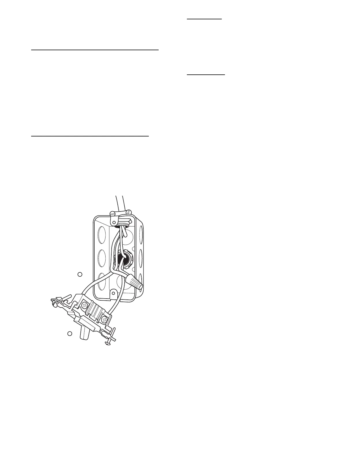
12. Complete electrical box wiring and installation. Connect
line voltage leads as shown in Fig. 24. Use best practices
(NEC in U.S. for wire bushings, strain relief, etc.)
13. Reinstall cover to J-- Box. Do not pinch wires between
cover and bracket.
POWER CORD INSTALLATION IN FURNACE
J--BOX
NOTE: Power cords must be able to handle the electrical
requirements listed in Table 7. Refer to power cord
manufacturer’s listings.
1. Remove cover from J-- Box.
2. Route listed power cord through 7/8--in. (22 mm) diameter
hole in J--Box.
3. Secure power cord to J--Box bracket with a strain relief
bushing or a connector approved for the type of cord used.
4. Secure field ground wire to green ground screw on J--Box
bracket.
5. Connect line voltage leads as shown in Fig. 24.
6. Reinstall cover to J-- Box. Do not pinch wires between
cover and bracket.
BX CABLE INSTALLATION IN FURNACE
J--BOX
1. Remove cover from J-- Box.
2. Route BX cable into 7/8--inch diameter hole in J-- Box.
3. Secure BX cable to J--Box bracket with connectors ap-
proved for the type of cable used.
4. Secure field ground wire to green ground screw on J--Box
bracket.
5. Connect line voltage leads as shown in Fig. 24.
6. Reinstall cover to J-- Box. Do not pinch wires between
cover and bracket.
A10141
Fig. 22 -- Field-- Supplied Electrical Box on Furnace Casing
24--V WIRING
Ma ke field 24--v connections at the 24--v t erminal strip. (Se e Fig. 24)
Connect terminal Y as shown in Fig. 38 f or proper cooling
operation. Use only AWG No. 18, color--coded, copper thermost at
wir e .
The 24--v circuit contains an automotive--type, 3--amp. fuse located
on the control. Any direct shorts during installation, service, or
maintenance could cause this fuse to blow. If fuse replacement is
required, use ONLY a 3--a mp. fuse of identi ca l size .
ACCESSORIES
1. Electronic Air Cleaner (EAC)
Connect an accessory Electronic Air Cleaner (if used) using
1/4--in female quick connect terminals to the two male 1/4--in
quick--connect te r m ina l s on the cont rol boar d marked EAC
and NEUTRAL. The terminals are rated for 115 VAC, 1.0
am ps maxi m um a nd ar e ene rgized during blower motor op-
erati on. (Se e Fig. 23)
2. Humidif i e r (HUM)
Connect an accessory 115 VAC, 1 amp. maximum humidifi-
er (if used) to the 1/4--in male quick--connect HUM terminal
and NEUTRA L 1/ 4--in quic k c onnect. The HU M te r m i nal is
energized when the blower starts during a call for heat. (See
Fig. 23)
NOTE: A field--supplied, 115--v controlled relay connected to
EAC terminals may be added if humidifier operation is desired
during blower operation.
NOTE: DO NOT connect furnace control HUM terminal to
HUM (humidifier) terminal on Thermidistatt, Zone Controller
or similar device. See Thermidistat, Zone Controller, thermostat,
or controller manufacturer’s instructions for proper connection.
NOTE: DO NOT connect furnace control HUM 115VAC
terminal to H (humidifier) terminal on humidity sensing
thermostat, or similar device. See humidity sensing thermostat,
thermostat, or controller manufacturer’s instructions for proper
connection.