13
To Relocate the Condensate Trap:
S Remove the knockout in the ca sing for the conde nsa t e trap.
S Insta l l the gromme t in the cas i ng when required for direct--vent
horizonta l applica tions.
S Orient the furnace in the desired position.
S Allow for 2 in. (51 mm) of cl ea r anc e undernea t h the fur nac e for the
condens ate trap and dra i n li ne.
S Fig. 11 show s the condensa t e trap and tubing bef or e and after
reloca tion in the horizontal ri ght position.
S Fig. 12 shows the condensat e trap and tubing be f ore and after
reloca tion in the horizontal le ft positi on.
S Refer to the appropriate figure to begin the tra p convers i on.
S Refer to Conde nsate Drain sect i on for informa tion how to instal l the
condens ate drain.
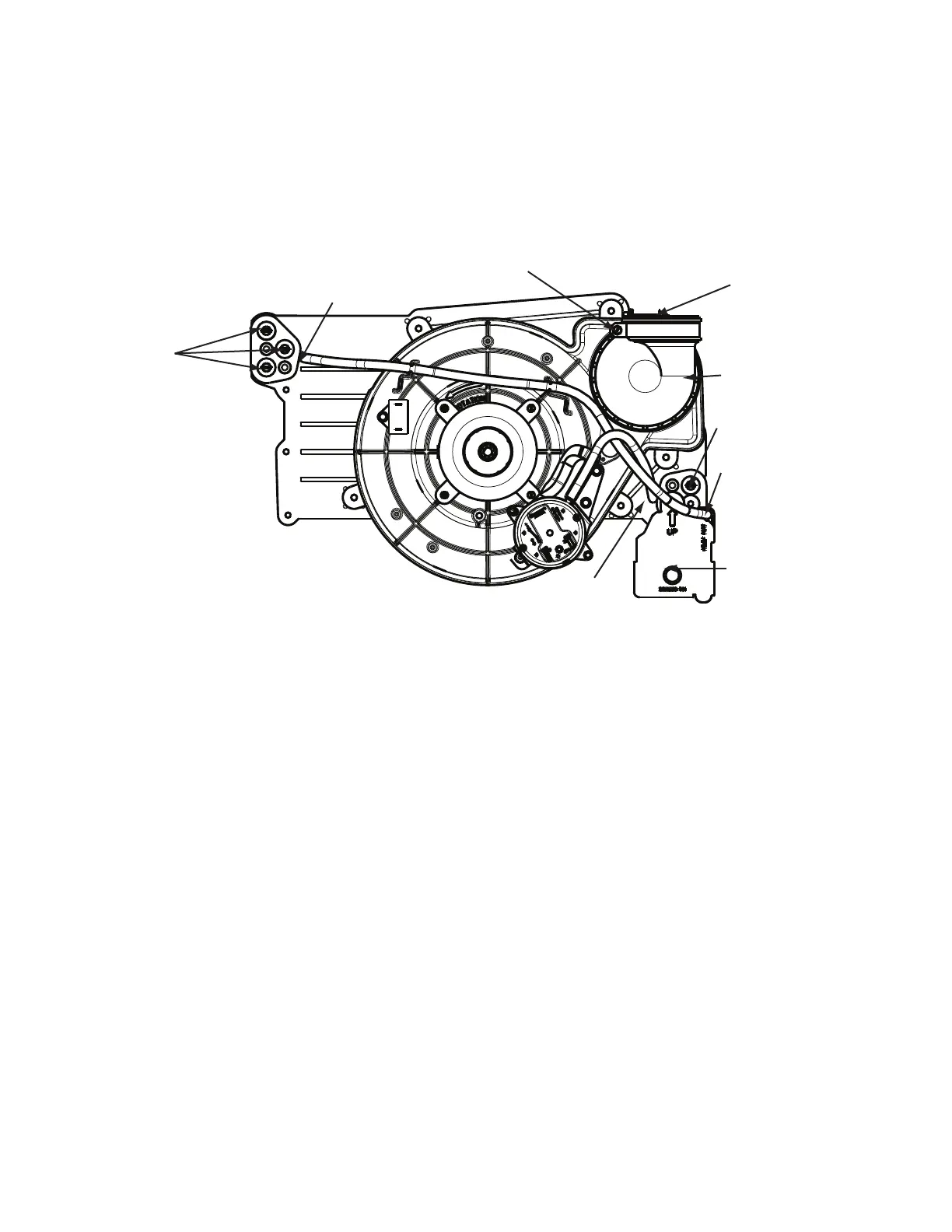
Condensate Trap
Relief Port
Collector Box
Plugs
Pressure Switch
Port
Condensate Trap
Outlet
Condensate Trap
Relief Port
Collector Box
Plug
Vent Elbow
Vent Elbow Clamp
Vent Pipe Clamp
UPFLOW TRAP CONFIGURATION
1 & 2 Stage Units
A11307
Fig. 9 -- Upflow Trap Configuration
(Appearance may vary)