68
motor failure. If the limit control does not function during
this test, the cause must be determined and corrected.
a. Run furnace for at least 5 minutes.
b. Gradually block off return air with a piece of cardboard or
sheet metal until the limit trips.
c. Unblock return air to permit normal circulation.
d. Burners will re--light when furnace cools down.
2. Check Pressure Switch(es)
This control proves operation of the draft inducer blower.
a. Turn off 115--v power to furnace.
b. Disconnect inducer motor lead wires from wire harness.
c. Turn on 115--v power to furnace.
d. Set thermostat to “call for heat” and wait 1 minute. When
low pressure switch is functioning properly, hot surface
igniter should NOT glow and control diagnostic light
flashes a status code 31. If hot surface igniter glows when
inducer motor is disconnected, shut down furnaceimmedi-
ately .
e. Determine reason low pressure switch did not function
properly and correct condition.
f. Turn off 115--v power to furnace.
g. Reconnect inducer motor wires, replace door, and turn on
115--v power.
h. Blower will run for 90 sec before beginning the call for
heat again.
i. Furnace should ignite normally.
Checklist
1. Put away tools and instruments. Clean up debris.
2. Verify that the jumper is removed from the TEST/TWIN
terminal. Verify that there is nothing plugged into the PLT
connector. (Note: If there is a jumper connector plugged
into PLT, remove it and discard.) See Fig. 38.
3. Verify that the Blower/Heat Off Delay jumpers are set as
desired. See Fig. 38 and 72.
4. Verify that the blower (lower door in upflow position) and
control (“Main” or upper door in upflow position) doors are
properly installed.
5. Verify that the Status LED glows. If not, check that the
power supply is energized and that the blower door is
secure. See Fig. 65 to interpret diagnostic codes.
6. Cycle test furnace with room thermostat to be sure that it
operates properly with the room thermostat. Check all
modes including Heat, Cool and Fan.
7. Check operation of accessories per manufacturer’s
instructions.
8. Review Owner’s Manual with owner.
9. Attach entire literature packet to furnace.
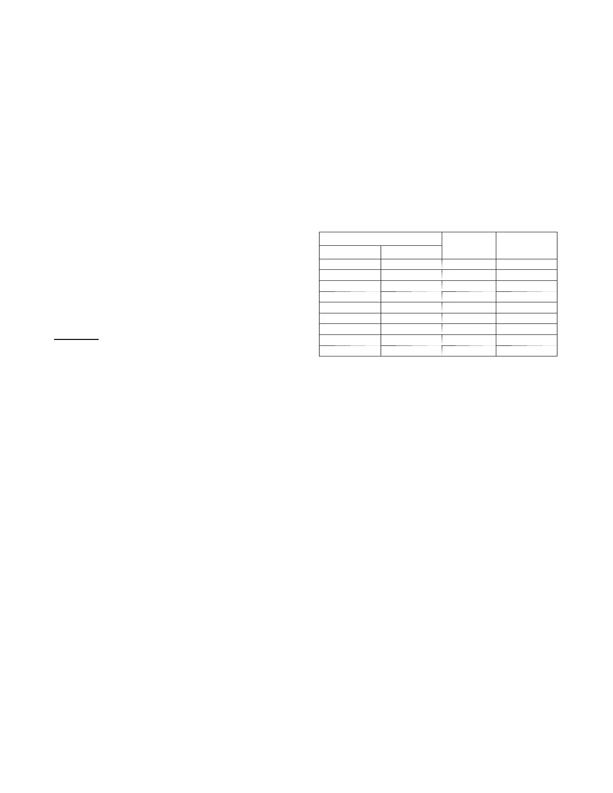
Table 19 – Altitude Derate Multiplier for U.S.A.
ALTITUDE
PERCENT
OF
DERATE
DERATE
MULTIPLIER
FACTOR*
FT. M
0–2000 0 --- 6 1 0 0 1.00
2001–3000 610---914 4 --- 6 0.95
3001–4000 914--- 1219 6 --- 8 0.93
4001–5000 1219--- 1524 8 --- 1 0 0.91
5001–6000 1524--- 1829 10---12 0.89
6001–7000 1829--- 2134 12---14 0.87
7001–8000 2134---2438 14---16 0.85
8001–9000 2438---2743 16---18 0.83
9001–10,000 2743---3048 18--- 20 0.81
*Derate mul tiplier factors are based on midpoint altitude for altitude range.