12
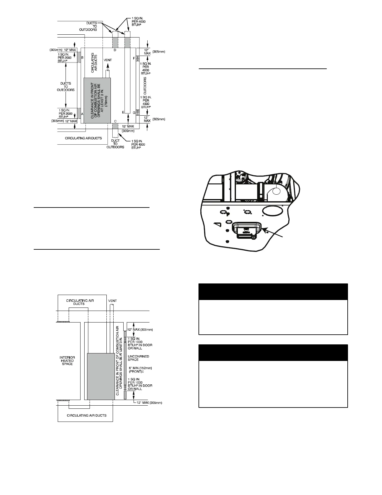
*Minimum dimensions of 3‐in. (76mm)
NOTE: Use any of the following combinations of openings:
A & B, C & D, D & E, F & G
L12F012
Fig. 6 -- Air for Combustion, Ventilation, and Dilution for
Outdoors
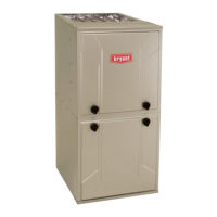
CONDENSATE TRAP
Condensate Trap -- Upflow Orientation
When the furnace is installed in the upflow position, it is not
necessary to relocate the condensate trap or associated tubing.
Refer to Fig. 9 for upflow condensate trap information. Refer to
Condensate Drain section for information how to install the
condensate drain.
Condensate Trap -- Downflow Orientation.
When the furnace is installed in the downflow position, the
condensate trap will be initially located at the upper left corner of
the collector box, as received from the factory. See the top image
in Fig. 10. When the furnace is installed in the downflow
orientation, the condensate trap must be relocated for proper
condensate drainage. See the bottom image in Fig. 10.
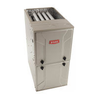
* Minimum opening size is 100 sq in. (64516 sq. mm) with
minimum dimensions of 3‐in. (76mm)
{ Minimum of 3‐in. (76mm) when type‐B1 vent is used.
L12F013
Fig. 7 -- Air for Combustion, Ventilation, and Dilution from
Indoors
To Relocate the Condensate Trap:
S Orient the fur nac e in the downflow pos ition.
S Fig. 10 shows the condensat e trap and tubing be f ore and after
reloca t ion. Re fe r to Fig. 10 t o begin the trap conver s ion.
S Refer to Conde nsate Drain sect i on for informa tion how to instal l the
condens ate drain.
Condensate Trap -- Horizontal Orientation.
Whe n t he fur nac e i s ins t al led in the hor i zont al r ight posi t ion, the
condens ate t r ap wi ll be initially located at the bottom of the collector
box, as received from the factory. See the top image in Fig. 11.
When the furnace is installed in the horizontal left position, the
condens ate tr ap will be initially located at the top of the collector box,
as received from the factory. See the top image in Fig. 12. In both
cas es the trap mus t be repos i ti oned on the colle ctor box for proper
condens ate draina ge. See the bott om im ages in Fi g. 11 and 12.
A field--supplied, accessory Horizontal Installation Kit (trap
grom met ) i s required for al l direc t--vent hori zont al ins ta l la tions ( onl y).
The kit contains a rubbe r casi ng grommet designed to seal bet wee n
the furnac e casing and the c ondensat e tra p. See Fig. 8.
Remove knockout.
Install grommet before
relocating condensate
trap.
NOTE: Trap grommet is required only for direct-vent
applications.
A11582
Fig. 8 -- Horizontal Drain Trap Grommet
The field--supplied, accessory horizontal drain trap grommet is
ONLY REQUIRED FOR DIRECT VENT APPLICATIONS.
It it NOT required for applications using single-- pipe or
ventilated combustion air venting.
NOTICE
The condensate trap extends below the side of the casing in
the horizontal position. A minimum of 2-- in. (51 mm) of
clearance is required between the casing side and the furnace
platform for the trap to extend out of the casing in the
horizontal position. Allow at least 1/4-- in. per foot (20 mm
per meter) of slope down.
NOTICE