24
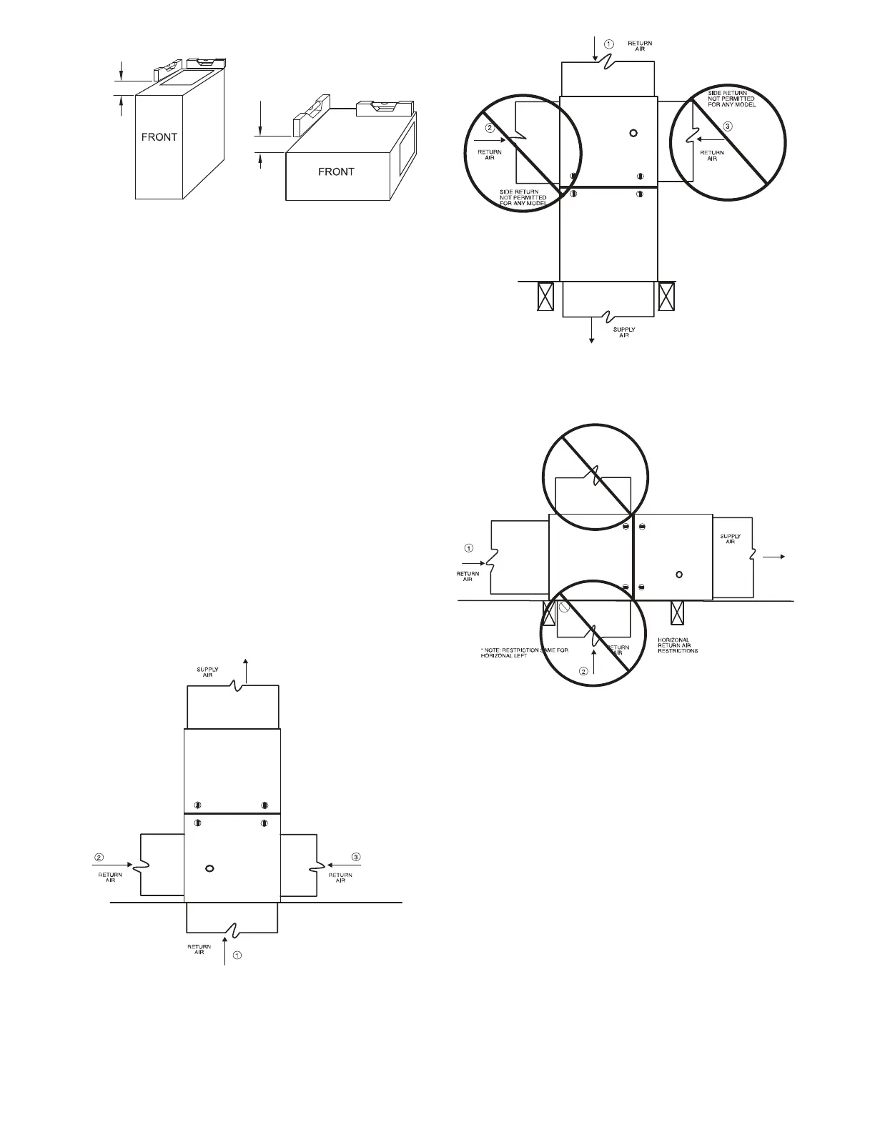
LEVEL 0-IN. (0 MM) TO
1/2-IN. (13 MM) MAX
UPFLOW OR
DOWNFLOW
HORIZONTAL
MIN 1/4-IN. (6 MM) TO
1/2-IN. (13 MM) MAX
A11237
Fig. 21 -- Furnace Pitch Requirements
Platform Furnace Support
Construct working platform at location where all required furnace
clearances are met. See T a ble 2 and Fig. 25. For furnaces with
1--in. (25 mm) clearance requirement on side, set furnace on
non-- combustible blocks, bricks or angle iron. For crawlspace
installations, if the furnace is not suspended from the floor joists,
the ground underneath furnace must be level and the furnace set on
blocks or bricks.
Suspended Furnace Support
The furnace must be supported under the entire length of the
furnace with threaded rod and angle iron. See Fig. 26. Secure
angle iron to bottom of furnace as shown.
Roll--Out Protection
Provide a minimum 12-- in. x 22-- in. (305 x 559 mm) piece of sheet
metal for flame roll--out protection in front of burner area for
furnaces closer than 12--in. (305 mm) above the combustible deck
or suspended furnaces closer than 12--in. (305 mm) to joists. The
sheet metal MUST extend underneath the furnace casing by 1 --in.
(25 mm) with the door removed.
The bottom closure panel on furnaces of widths 17--1/2--in. (445
mm) and larger may be used for flame roll-- out protection when
bottom of furnace is used for return air connection. See Fig. 25 for
proper orientation of roll--out shield.
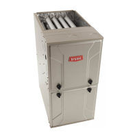
ANY COMBINATION OF 1, 2, OR 3 PERMITTED.
A11036
Fig. 22 -- Upflow Return Air Configurations and Restrictions
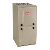
A11037
Fig. 23 -- Downflow Return Air Configurations
and Restrictions
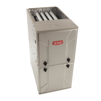
HORIZONTAL
RETURN NOT
PERMITTED FOR
ANY MODEL
A13109
Fig. 24 -- Horizontal Return Air Configurations
and Restrictions