912SE: Installation, Start-up, Operating and Service and Maintenance Instructions
Manufacturer reserves the right to change, at any time, specifications and designs without notice and without obligations.
41
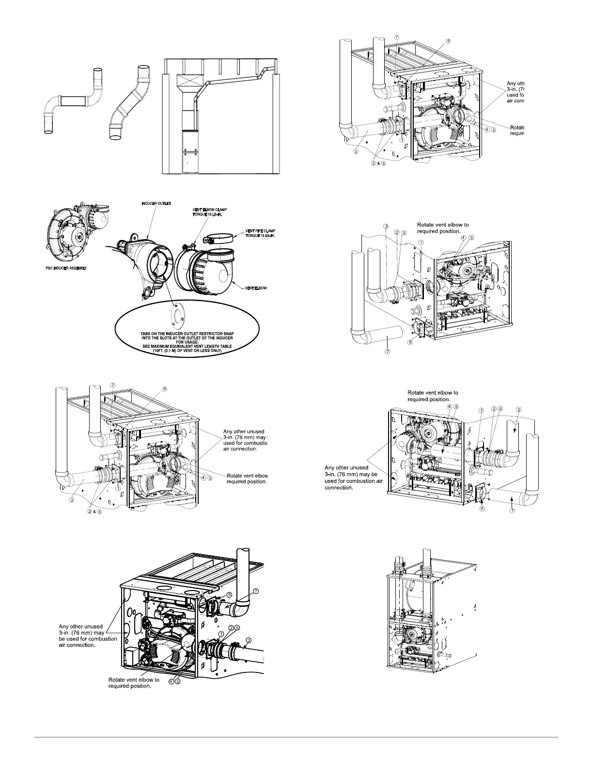
3. Tighten the clamp around the vent elbow. Torque the clamp to 15
lb-in. See Fig. 54 - Fig. 57.
A14546
Fig. 52 – Near Furnace Vent Connections
A170006
Fig. 53 – Inducer Vent Elbow
A230010
Representative drawing only, some models may vary.
UPFLOW LEFT CONFIGURATION
A230009
Representative drawing only, some models may vary.
UPFLOW RIGHT CONFIGURATION
A230011
Representative drawing only, some models may vary.
UPFLOW VERTICAL VENT
Fig. 54 – Upflow Configurations (Appearance may vary)
See “Notes for Venting Options”
A11311A
Representative drawing only, some models may vary.
DOWNFLOW LEFT CONFIGURATION
A230013
Representative drawing only, some models may vary.
DOWNFLOW RIGHT CONFIGURATION
A11313A
Representative drawing only, some models may vary.
Avoid short horizontal offsets with 90
deg. El b o w s. Short offset s can b e
difficult to slope and may trap con-
densate.
Use 45 deg. Elbows where
possible, to ensure conden-
sate drainage.
Slope vent pipe back to the
furnace at least ¼” per foot
Requires Accessory Internal Vent Kit.
See Product Data for current kit number.