12
CONDENSATE TRAP
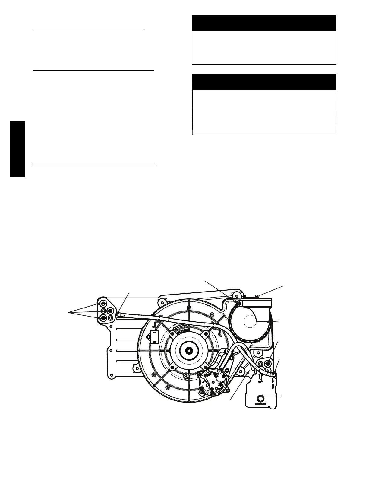
Condensate Trap -- Upflow Orientation
When the furnace is installed in the upflow position, it is not
necessary to relocate the condensate trap or associated tubing.
Refer to Fig. 8 for upflow condensate trap information. Refer to
Condensate Drain section for information how to install the
condensate drain.
Condensate Trap -- Downflow Orientation.
When the furnace is installed in the downflow position, the
condensate trap will be initially located at the upper left corner of
the collector box, as received from the factory. See the top image
in Fig. 9. When the furnace is installed in the downflow
orientation, the condensate trap must be relocated for proper
condensate drainage. See the bottom image in Fig. 9.
To Relocate the Condensate Trap:
S Orient the furnace in the downflow posi t ion.
S Fig. 9 s hows the condensate trap and t ubing bef ore and after
relocat ion. Re fer to Fi g. 9 to be gi n the trap conversion.
S Refer t o Condensate Drain se ction for inf or m ati on how to ins tall t he
condensate drain.
Condensate Trap -- Horizontal Orientation.
Whe n t he fur nace i s installed in t he hor i zontal r ight position, the
condensate t r ap wil l be initially located at the bottom of the collector
box, as received from the factory. See the top image in Fig. 10.
When the furnace is installed in the horizontal left position, the
condensate tr ap wi ll be i nitially located at the top of the collector box,
as received from the factory. See the top image in Fig. 11. In both
cases t he trap must be re positione d on the collector box for pr oper
condensate drai nage . See the bot t om im ages i n Fig. 10 a nd 11.
A field--supplied, accessory Horizontal Installation Kit (trap
grom met) is re quired f or a ll direc t--vent horizontal i nsta llati ons ( only).
The kit cont ains a r ubber ca sing grommet des i gned t o s eal between
the furna ce casing a nd the c ondensate t r ap. See Fig. 17.
The field--supplied, accessory horizontal drain trap grommet is
ONLY REQUIRED FOR DIRECT VENT APPLICATIONS.
It it NOT required for applications using single--pipe or
ventilated combustion air venting.
NOTICE
The condensate trap extends below the side of the casing in
the horizontal position. A minimum of 2--in. (51 mm) of
clearance is required between the casing side and the furnace
platform for the trap to extend out of the casing in the
horizontal position. Allow at least 1/4 --in. per foot (20 mm
per meter) of slope down.
NOTICE
To Relocate the Condensate Trap:
S Remove the knockout in the casing for the conde nsate trap.
S Instal l the gromme t in the casing when required for direct--vent
horizontal appl ications.
S Orient the furnace in the desired position.
S Allow for 2 in. (51 mm) of clearance underneath the fur nace for the
condensate trap and dr ain line.
S Fig. 10 s hows the condensate trap and t ubing bef ore and after
relocation i n the horizontal r ight pos iti on.
S Fig. 1 1 shows the conde nsate trap and t ubing bef ore and after
relocation i n the horizontal l eft posi tion.
S Refer t o the appropria te figure to begi n the tra p conve r sion.
S Refer t o Condensate Drain se ction for inf or m ati on how to ins tall t he
condensate drain.
Condensate Trap
Relief Port
Collector Box
Plugs
Pressure Switch
Port
Condensate Trap
Outlet
Condensate Trap
Relief Port
Collector Box
Plug
Vent Elbow
Vent Elbow Clamp
Vent Pipe Clamp
UPFLOW TRAP CONFIGURATION
1 & 2 Stage Units
A11307
Fig. 8 -- Upflow Trap Configuration
(Appearance may vary)
922SA