51
3. Slide assembled kit with rain shield REMOVED through
hole.
NOTE: Do not allow insulation or other materials to accumulate
inside of pipe assembly when installing it through hole.
4. Locate assembly through sidewall with rain shield posi-
tioned no more than 1−in. (25 mm) from wall as shown in
Fig. 53.
5. Disassemble loose pipe fittings. Clean and cement using
same procedures as used for system piping. DO NOT CE-
MENT POLYPROPYLENE FITTINGS.
2-Pipe and 1-Pipe Vent Termination
NOTE: Follow the instructions of the vent terminal manufacturer.
These instructions are provided as a reference, only.
RECOMMENDED SUPPORT FOR VENT
TERMINATIONS
It is recommended that sidewall vent terminations in excess of
24 inches (0.6 M) in vertical length be supported by EITHER
the Direct Vent Termination Kit shown in Table 12 or by
field−supplied brackets or supports fastened to the structure.
NOTICE
Determine an appropriate location for termination kit using the
guidelines provided in section “Locating The Vent Termination” in
this instruction.
1. Cut two holes, one for each pipe, of appropriate size for
pipe size being used.
2. Loosely install elbow in bracket (if used) and place as-
sembly on combustion−air pipe.
3. Install bracket as shown in Fig. 53 and 55.
NOTE: For applications using vent pipe option indicated by
dashed lines in Fig. 53 and 54, rotate vent elbow 90 from
position.
4. Disassemble loose pipe fittings. Clean and cement using
same procedures as used for system piping. DO NOT CE-
MENT POLYPROPYLENE FITTINGS.
(Direct Vent / 2-Pipe System ONLY)
When two or more furnaces are vented near each other, two vent
terminations may be installed as shown in Fig. 53, but next vent
termination, or pair of vent terminations, must be at least 36 in.
(914 mm) away from the first two terminations. It is important that
vent terminations be made as shown in Fig. 53 to avoid
recirculation of vent gases.
Inducer Outlet Restrictor
To improve efficiency and operation of 60K or 100K BTUH input
models on very short vent systems, an inducer outlet restrictor is
required to be installed on the outlet of the inducer assembly. The
outlet restrictor is shown in the footnote of Table 16 −Maximum
Equivalent Vent Length. See Table 16 for usage, part numbers and
sourcing of 60K and 100K inducer outlet restrictors.
To determine if the outlet restrictor is required, see Table 16.
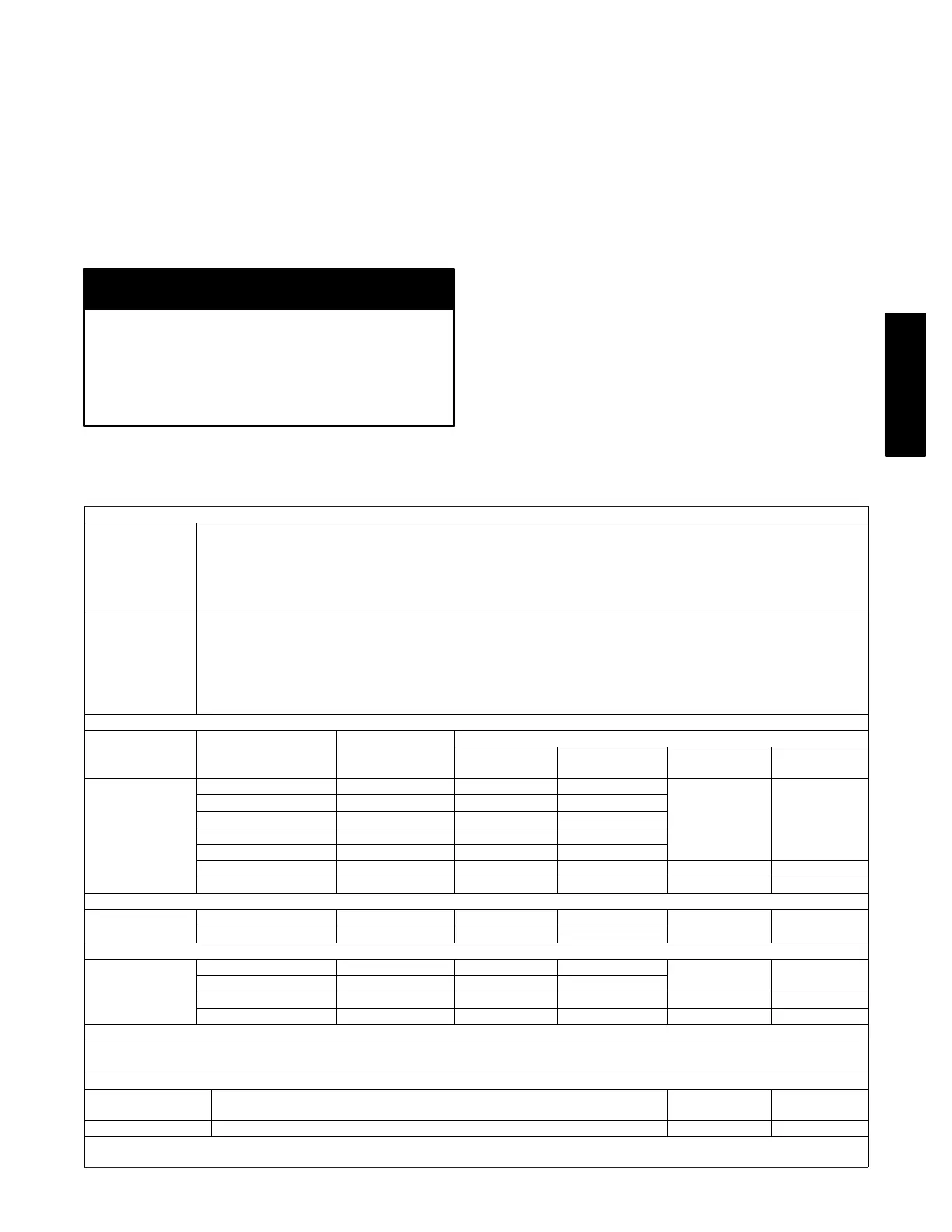
Table 14 – Approved Combustion-Air and Vent Pipe, Fitting and Cement Materials (U.S.A. Installations)
MATERIALS
USA
1. All pipe, fittings, primers*, and solvents* must conform to American National Standards Institute (ANSI) stan
dards and American Society for Testing and Materials (ASTM) standards or ULC S636 where required by
code.
2. See Table below for approved materials for use in the U.S.A.
3. ULC S636 vent systems must be composed of pipe, fittings, cements, and primers from the same supplier.
4. Factory accessory concentric vent kits are ULC S636 listed.
CANADA
1. Installation in Canada must conform to the requirements of CAN/CSA B149 code.
2. Vent systems must be composed of pipe, fittings, cements, and primers from the same supplier and listed to
ULC S636.
3. Not all materials below may be approved or listed to ULC S636.
4. Royal Pipe and IPEX are approved suppliers of ULC S636 pipe, fittings, cements and primers*.
5. Factory accessory concentric vent kits are ULC S636 listed for use with Royal Pipe and IPEX venting sys
tems.
Material Description Type
ASTM or ULC Specification
Pipe Fittings
Solvents
Primers*
Cements
PVC
Pressure Pipe Schedule 40 D1785 D2665
F656 D2564
DWV Schedule 40 D1785 D2665
Cellular Core Schedule 40 F891 D2466
SDR 26 N/A D2241 N/A
SDR21 N/A D2241 N/A
IPEX Schedule 40 ULC S636 ULC S636 ULC S636 ULC S636
Royal Pipe Schedule 40 ULC S636 ULC S636 ULC S636 ULC S636
ABS
ABS Schedule 40 D1527 D2468
Clear Cleaner
For ABS†
D2235
Cellular Core DWV Schedule 40 F628 D2661
CPVC
Pressure Pipe Schedule 40 F441 F438
F656 F493
SDR N/A F442 N/A
IPEX Schedule 40 ULC S636 ULC S636 ULC S636 ULC S636
Royal Pipe Schedule 40 ULC S636 ULC S636 ULC S636 ULC S636
*Colored or tinted solvents or primers must be used where required by code in the USA
†ABS plastic does not require a primer before solvent cementing. A cleaner for ABS is recommended to remove any surface residue. ABS
cleaners are not subject to ASTM standards.
Polypropylene Approved Manufacturer
Solvents
Primers
Cements
Poly Pro® M & G Dura Vent Not Permitted Not Permitted
NOTE: Polypropylene vent systems are UL-1738 and ULC S636 listed and assembled using mechanical fastening systems supplied by
the vent manufacturer.
986TB