86
A11392
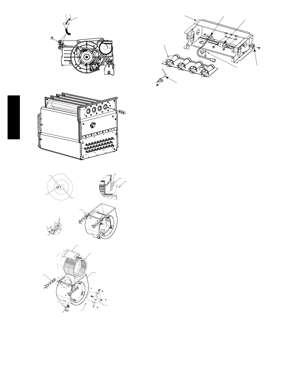
Fig. 68 − Priming Condensate Trap
A11273
Fig. 69 − Cleaning Heat Exchanger Cell
SET SCREW
MOTOR WHEEL HUB
MOTOR SHAFT FLAT
SCREW
MOTOR ARM
GROMMET
SCREW LOCATION
BLOWER HSG ASSY
BRACKET
BRACKET
ENGAGEMENT
SEE DETAIL
A
CAPACITOR
OR POWER CHOKE
(WHEN USED)
BRACKET
SCREW
(GND)
BLOWER HSG ASSY
MOTOR, BLOWER
WHEEL, BLOWER
CUTOFF, BLOWER
DETAIL
A
A11584
Fig. 70 − Blower Assembly
FLAME SENSOR
(BELOW BURNER)
FLAME ROLLOUT
SWITCH
BRACKET, IGNITER
IGNITER
BURNER SUPT. ASSY
BURNER ASSY
A11403
Fig. 71 − Burner Assembly
SEQUENCE OF OPERATION
NOTE: Furnace control must be grounded for proper operation or
else control will lock out. Control is grounded through
green/yellow wire routed to gas valve and burner box screw. Using
the schematic diagram in Fig. 73, follow the sequence of operation
through the different modes. Read and follow the wiring diagram
very carefully.
NOTE: If a power interruption occurs during a call for heat
(W/W1 or W/W1−and−W2), the control will start a 90−sec
blower−only ON period two sec after power is restored, if the
thermostat is still calling for gas heating. The amber LED light will
flash code 12 during the 90−sec period, after which the LED will
be ON continuous, as long as no faults are detected. After the
90−sec period, the furnace will respond to the thermostat normally.
The blower door must be installed for power to be conducted
through the blower door interlock switch ILK to the furnace
control CPU, transformer TRAN, inducer motor IDM, blower
motor BLWM, hot−surface igniter HSI, and gas valve GV.
1. Two−Stage Heating (Adaptive Mode) with Single−Stage
Thermostat
See Fig. 38 and 39 for thermostat connections
NOTE: The low−heat only switch SW1−2 selects either the
low−heat only operation mode when ON, (see item 2. below) or
the adaptive heating mode when OFF in response to a call for heat.
See Fig. 64. When the W2 thermostat terminal is energized it will
always cause high−heat operation when the R−to−W circuit is
closed, regardless of the setting of the low−heat only switch. This
furnace can operate as a two−stage furnace with a single−stage
thermostat because the furnace control CPU includes a
programmed adaptive sequence of controlled operation, which
selects low−heat or high−heat operation. This selection is based
upon the stored history of the length of previous gas−heating
periods of the single−stage thermostat.
The furnace will start up in either low− or high−heat. If the furnace
starts up in low−heat, the control CPU determines the low−heat
on−time (from 0 to 16 minutes) which is permitted before
switching to high−heat.
If the power is interrupted, the stored history is erased and the
control CPU will select low−heat for up to 16 minutes and then
switch to high−heat, as long as the thermostat continues to call for
heat. Subsequent selection is based on stored history of the
thermostat cycle times.
The wall thermostat “calls for heat”, closing the R−to−W circuit.
The furnace control performs a self−check, verifies the low−heat
and high−heat pressure switch contacts LPS and HPS are open, and
starts the inducer motor IDM in high−speed.
a. Inducer Prepurge Period
986TB