76
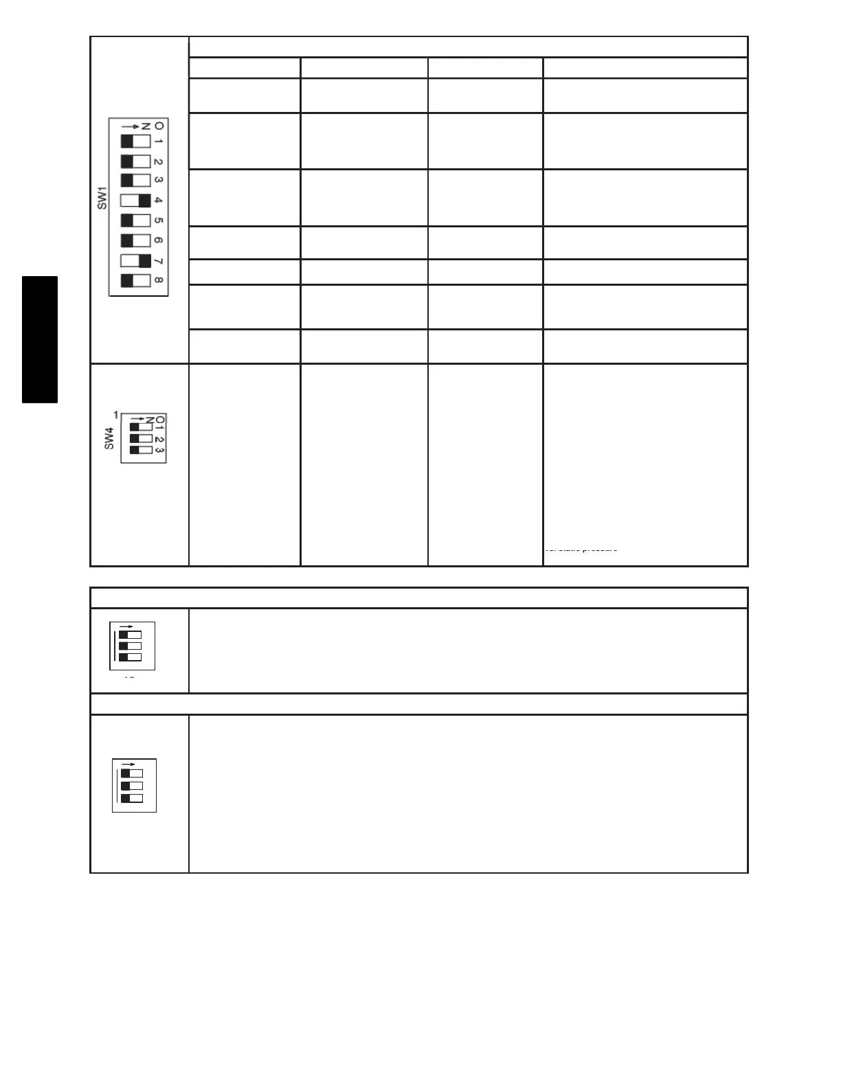
SETUP SWITCH SWITCH NAME NORMAL POSITION DESCRIPTION OF USE
SW1-1 Status Code Recovery OFF
Turn ON to retrieve up to 7 stored status codes for
troubleshooting assistance when R thermostat
lead is disconnected.
SW1-2
Low Heat Only
(Adaptive Heat Mode when
SW1-2 is OFF)
OFF
When SW1-2 is OFF allows 2-stage operation with
a single stage thermostat. Turn ON when using
2-stage thermostat to allow Low Heat operation
when R to W/W1 closes and High Heat operation
when R to W/W1 and W2 close.
Furnace Setup Switch Description
SW1-3 Low Heat Rise Adjustment OFF
Turn ON to increase Low Heat airflow by 18%.
This compensates for increased return air
temperature caused with bypass humidifier.
SW1-4 Comfort/Efficiency Adjustment ON
Turn ON to decrease low heat airflow 20% for 90%
models or 16% for 80% models & high heat airflow
15% for 90% models or 10% for 80% models.
SW1-5 CFM per ton adjust OFF
Turn ON for 400 CFM per ton, Turn OFF for 350
CFM per ton. See also SW4.
Turn ON to initiate Component Self Test for
SW1-6 Component Self Test OFF
troubleshooting assistance when R thermostat
lead is disconnected. Turn OFF when Self Test is
completed.
SW1-7 & SW1-8 Blower OFF delay ON or OFF
Blower Off Delay time – adjustable 90 seconds to
180 seconds. See table in Adjustments section or
refer to unit wiring diagram.
Allows additional CFM per ton selections when
used with SW 1-5
325 CFM per ton (nominal) when SW 4-3 ON and
SW 1-5 OFF
SW4-3
CFM per ton Adjust
OFF
350 CFM per ton (nominal) when SW 4-3 OFF and
SW 1-5 OFF
370 CFM per ton (nominal) when SW4-3 ON and
SW 1-5 ON
400 CFM per ton (nominal) when SW 1-5 ON and
SW 4-3 OFF
See Air Delivery Tables for model specific CFM
AIR CONDITIONING (A/C) SETUP SWITCHES
SW 2, AC (Cooling Airflow) SETUP SWITCHES
The AC setup switch selects desired cooling or high stage cooling (two stage units) airflow.
O
N
1
2
3
1
SW2
See Air Delivery Tables for specific switch settings
CONTINUOUS FAN (CF) SETUP SWITCHES
SW 3, CF (Continuous Fan) SETUP SWITCHES
The CF setup switch selects desired Continuous Fan Airflow
The CF switch position is the low cooling airflow selection for two stage cooling units.
O
N
1
2
3
1
SW3
The CFM values in the Air Delivery Tables for SW 3 settings are the same as SW 2 settings.
SW 3 cannot be set for airflow higher than SW 2
See Air Delivery Tables for specific switch settings
CF
A13309
Fig. 64 − Furnace Setup Switches and Description (Continued)
986TB