—
24
—
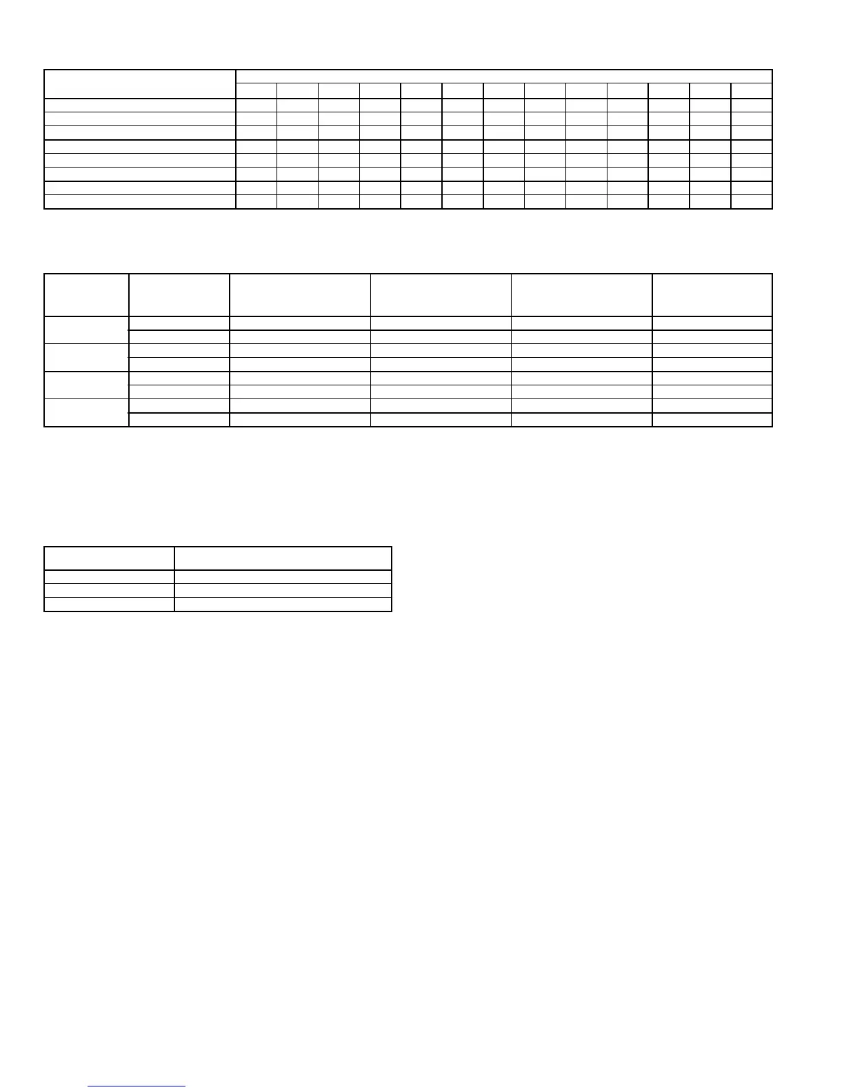
Table 13 — Fan Rpm at Motor Pulley Settings*
*Approximate fan rpm shown.
†Indicates standard drive package.
**Indicates alternate drive package.
††Due to belt and pulley size, pulley cannot be set to this number of turns open.
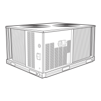
Table 14 — Evaporator-Fan Motor Performance
LEGEND
*Extensive motor and electrical testing on these units ensures that the full horse-
power (brake kilowatt) range of the motors can be utilized with confidence. Using
your fan motors up to the horsepower (brake kilowatt) ratings shown in this table
will not result in nuisance tripping or premature motor failure. Unit warranty will
not be affected.
NOTE:
All indoor-fan motors 5 hp and larger meet the minimum efficiency re-
quirements as established by the Energy Policy Act of 1992 (EPACT) effective
October 24, 1997.
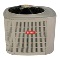
Table 15 — Evaporator-Fan Motor Efficiency
NOTE:
All indoor-fan motors 5 hp and larger meet the minimum efficiency
requirements as established by the Energy Policy Act of 1992 (EPACT) effective
October 24, 1997.
XII. BASE UNIT OPERATION
A. Cooling, Units without EconoMi$er
When thermostat calls for cooling, terminals G and Y1 are
energized. The indoor (evaporator) fan contactor (IFC), and
compressor contactor no. 1 (C1) are energized and evaporator-
fan motor, compressor no. 1 and condenser fans start. The
condenser-fan motors run continuously while unit is cooling. If
the thermostat calls for a second stage of cooling by energizing
Y2, compressor contactor no. 2 (C2) is energized and compres-
sor no. 2 starts.
B. Heating, Units without EconoMi$er (If Accessory or
Optional Heater is Installed)
Upon a call for heating through terminal W1, IFC and
heater contactor no. 1 (HC1) are energized. On units
equipped for 2 stages of heat, when additional heat is
needed, HC2 is energized through W2.
C. Cooling Units with EconoMi$er
When the OAT is above the ECON SP set point and the room
thermostat calls for Stage 1 cooling (R to G + Y1), the indoor-fan
motors (IFM) is energized and the EconoMi$er damper modu-
lates to minimum position. The compressor contactor and OFC
are energized to start the compressor and outdoor-fan motor
(OFM). After the thermostat is satisfied, the damper modulates
to the fully closed position when the IFM is deenergized.
When the OAT is below the ECON SP setting and the room
thermostat calls for Stage 1 cooling (R to G + Y1), the
EconoMi$er modulates to the minimum position when the
IFM is energized. The EconoMi$er provides Stage 1 of cooling
by modulating the return and outdoor air dampers to main-
tain a 55 F supply air set point. If the supply-air temperature
(SAT) is greater than 57 F, the EconoMi$er modulates open,
allowing a greater amount of outdoor air to enter the unit. If
the SAT drops below 53 F, the outdoor air damper modulates
closed to reduce the amount of outdoor air. When the SAT is
between 53 and 57 F, the EconoMi$er maintains its position.
If outdoor air alone cannot satisfy the cooling requirements
of the conditioned space, and the OAT is above the MECH
CLG LOCKOUT set point, the EconoMi$er integrates free
cooling with mechanical cooling. This is accomplished by the
strategies below.
NOTE: Compressors have a two-minute Minimum On and
Minimum Off, which are accomplished by the strategies below.
1. If Y1 is energized, and the room thermostat calls for
Y2 (2-stage thermostat), the compressor and OFC are
energized. The position of the EconoMi$er damper is
maintained at its current value.
2. If Y1 is energized for more than 20 minutes, and Y2 is
not energized (whether or not a 2-stage thermostat is
used), the compressor and OFC are energized. The
position of the EconoMi$er damper is maintained at
its current value.
3. If Y1 is energized, and compressor no. 1 is already
energized (see Step 2) and the room thermostat calls
for Y2, compressor no. 1 continues to operate. If Y2
remains energized for more than 20 minutes, com-
pressor no. 2 is energized.
UNIT
558F
MOTOR PULLEY TURNS OPEN
0
1
/
2
11
1
/
2
22
1
/
2
33
1
/
2
44
1
/
2
55
1
/
2
6
180†
†† †† †† †† 1021 1002 984 965 947 928 910 891 873
180**
†† †† †† †† 1200 1178 1156 1134 1112 1091 1069 1047 1025
210†
†† †† 1095 1077 1058 1040 1021 1002 984 965 947 928 910
210**
†† †† 1287 1265 1243 1222 1200 1178 1156 1134 1112 1091 1069
240†
†† †† †† †† 1151 1132 1114 1095 1077 1058 1040 1021 1002
240**
†† †† †† †† 1369 1347 1325 1303 1281 1259 1237 1215 1193
300†
†† †† 1283 1269 1247 1225 1203 1182 1160 1138 1116 1095 1066
300**
†† †† †† †† 1551 1524 1497 1470 1443 1415 1388 1361 1332
UNIT
558F
UNIT
VOLTAGE
MAXIMUM
ACCEPTABLE
CONTINUOUS
BHP*
MAXIMUM
ACCEPTABLE
CONTINUOUS
BkW*
MAXIMUM
ACCEPTABLE
OPERATING
WATTS
MAXIMUM
AMP DRAW
180
208/230 6.13 4.57 5,180 15.8
460 6.13 4.57 5,180 7.9
210
208/230 5.90 4.40 5,180 15.8
460 5.90 4.40 5,180 7.9
240
208/230 8.70 6.49 7,915 22.0
460 9.50 7.08 8,640 13.0
300
208/230 10.20 7.61 9,510 28.0
460 11.80 8.80 11,000 14.6
BHP —
Brake Horsepower
BkW —
Brake Kilowatts
MOTOR
HORSEPOWER
MOTOR EFFICIENCY
(%)
5 Hp
87.5
7.5 Hp
88.5
10.0 Hp
89.5