—
7
—
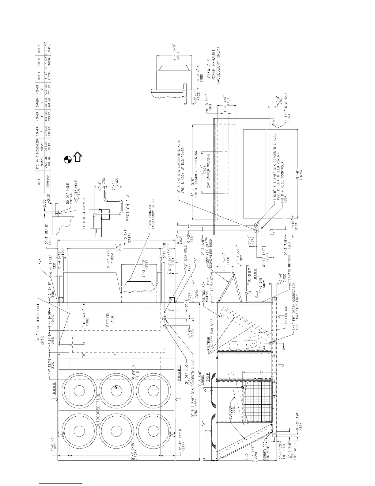
Fig. 6 — Base Unit Dimensions — 558F300
NOTES:
1. Refer to print for roof curb accessory dimensions.
2. Dimensions in ( ) are in millimeters.
3. Center of gravity.
4. Direction of airflow.
5. Ductwork to be attached to accessory roof curb only.
6. Minimum clearance:
Rear: 7
′
-0
″
(2134) for coil removal. This dimension can be reduced to 4
′
-0
″
(1219) if
conditions permit coil removal from the top.
Left Side: 4
′
-0
″
(1219) for proper condenser coil airflow.
Front: 4
′
-0
″
(1219) for control box access.
Right Side: 4
′
-0
″
(1219) for proper operation of damper and power exhaust if so
equipped.
Top: 6
′
-0
″
(1829) to assure proper condenser fan operation.
Local codes or jurisdiction may prevail.
7. With the exception of clearance for the condenser coil and the damper/power
exhaust as stated in Note #6, a removable fence or barricade requires no clearance.
8. Dimensions are from outside of corner post. Allow 0
′
-
5
/
16
(8) on each side for top
cover drip edge.
9. A 90 degree elbow must be installed on the supply ductwork below the unit discharge
for units equipped with electric heaters.
10. The lower forklift braces must be removed prior to setting unit on roof curb.