—8—
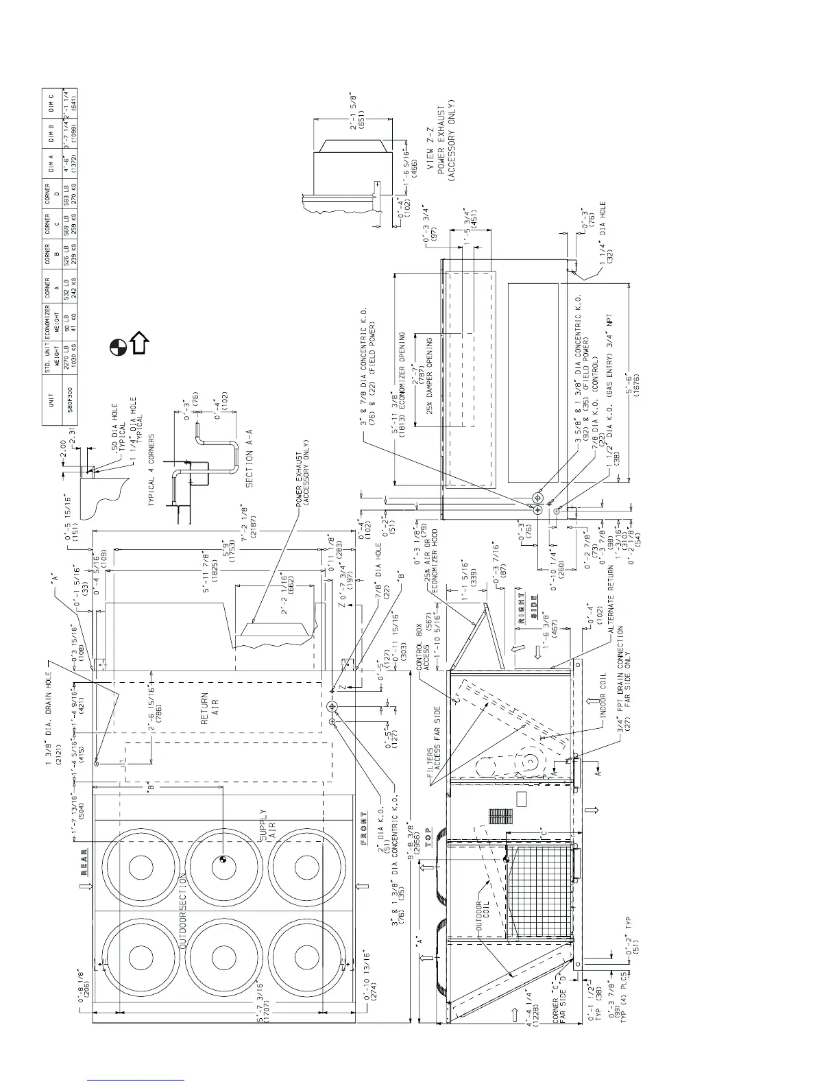
Fig. 6 — Base Unit Dimensions — 580F300
NOTES:
1. Refer to print for roof curb accessory dimensions.
2. Dimensions in ( ) are in millimeters.
3. Center of Gravity.
4. Direction of airflow.
5. Ductwork to be attached to accessory roof curb only.
6. Minimum clearance:
•Rear: 7′-0″ (2134) for coil removal. This dimension can be reduced to 4′-0″ (1219) if con-
ditions permit coil removal from the top.
•4′-0″ (1219) to combustible surfaces, all four sides (includes between units).
•Left side: 4′-0″ (1219) for proper condenser coil airflow.
•Front: 4′-0″ (1219) for control box access.
• Right side: 4′-0″ (1219) for proper operation of damper and power exhaust if so equipped.
•Top: 6′-0″ (1829) to assure proper condenser fan operation.
• Bottom: 14″ (356) to combustible surfaces (when not using curb).
• Control box side: 3′-0″ (914) to ungrounded surfaces, non-combustible.
• Control box side: 3′-6″ (1067) to block or concrete walls, or other grounded surfaces.
• Local codes or jurisdiction may prevail.
7. With the exception of clearance for the condenser coil and the damper/power exhaust as
stated in Note #6, a removable fence or barricade requires no clearance.
8. Dimensions are from outside of corner post. Allow 0′-
5
/
16
″ (8) on each side for top cover
drip edge.
9. The lower forklift brace must be removed prior to setting unit on roof curb.
 Loading...